![65 Years of Innovation and Experience [default]](https://www.robbinstbm.com/wp-content/uploads/2017/04/Side-Bar-Blue-Blocks_70-Years.jpg)
 The Channel Tunnel, one of the world’s most famous tunnels, is a 50 km (31 mi) tunnel under the English Channel linking Great Britain to France. This link consists of three parallel tunnels running for 39 km (24.2 mi) under the sea. Two Main Rail Tunnels, about 30 m (98 ft) apart, carry trains from the north and from the south. In between the two tunnels is the Channel Service Tunnel, which is connected by cross-passages to the main tunnels. This service tunnel allows maintenance workers to access the rail tunnels at regular intervals.
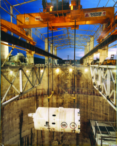
The contractor for the project, Transmanche-Link (TML) chose five Robbins TBMs to participate in boring the crossings. TBMs were deployed at both the U.K. and France Terminals.
The majority of the Channel Tunnel passes through chalk marl, much of it faulted. Below the Chalk Marl is a thin 2 m (6.5 ft) band of permeable Glauconitic Marl. This rock is a weak sandstone with a stronger rock strength than the Chalk. The bottom of the tunnels pass through stiff clay with some swelling characteristics. The Chalk is much more faulted and prone to water inflows on the French side of the tunnels.
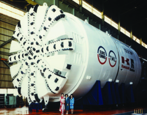 Robbins built five machines for this project, each designed for the geology of a specific length of tunnel.
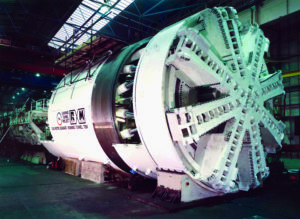
The high water pressures predicted in the folded and faulted chalk on the French side required the use of three Earth Pressure Balance machines (EPBMs). These machines featured sealed cutter chambers to withstand high water pressures and screw conveyors to carry the cut material from the face.
Robbins built two EPBMs for the French side of each Main Rail Tunnel. These 1,100 tonne (1,200 ton), 8.8 m (29 ft) diameter machines had a cutterhead thrust of 19,613 kN (4,413,000 lb) and generated a maximum torque of 12,748,645 N-m (9,410,000 lb-ft).
The undersea French side of the Channel Service Tunnel also required an EPBM. This machine featured a 5.6 m (18 ft) diameter cutterhead, a cutterhead thrust of 39,227 kN (8,837,000 lb), and a maximum torque of 3,510,781 N-m (2,591,000 lb-ft).
Two Double Shield TBMs were built for the U.K. terminal because fewer water inflows were predicted. Robbins designed these machines to withstand unstable and faulted rock conditions. The 8.36m (27 ft) diameter machines included 13 inch (330 mm) cutters and 65,871 kN (14,821,000 lb) of thrust. The machines generated a maximum 5,727,084 N-m (4,227,660 lb-ft) of torque.
 Machines were deployed on both sides of the tunnels in December 1987. The three French seaward TBMs encountered water inflows almost immediately, forcing the use of the sealed mode of operation much earlier than anticipated. The sealed cutterheads of the machines could withstand 10 bar (145 psi) of water pressure; however, additional measures were required to seal the remainder of the machines against water inflow.
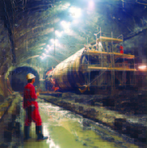
The tail shields of the TBMs were fitted with multiple rows of wire brush seals that pressed against the outside diameter of the concrete segment lining. Grease was injected into wire brushes and the 100 mm (4 in) space between the metallic brushes and the tunnel lining. Grout lines were fitted into the tail shield allowing fine cement grout to be injected into the 152 mm (6 in) annulus between the tunnel lining and the ground. This method sealed the tunnel lining as the TBMs advanced. In spite of the difficult conditions, advance rates improved throughout the boring with the Robbins service tunnel machine averaging 714 m (2,342 ft) per month for the project.
The U.K. machines also experienced some difficult tunneling conditions at the outset. Unforeseen water inflows in a 3.2 km (2.0 mi) stretch caused the machines to slow their progress as each section of tunnel had to be grouted in advance of boring. After passing through this section of tunnel, the machines experienced no further difficulties and began averaging 149 m (490 ft) a week. The Robbins machines on the U.K. side averaged 873 m (2,864 ft) per month and set world records for a best day of 75.5 m (247.7 ft), a best week of 428 m (1,404 ft), and a best month of 1,719 m (5,640 ft) — all of which have yet to be beaten.
 Muck transport on both sides of the tunnel was complicated but worked well. In the U.K. a rail system of 500 muck cars transported muck back to the access adit at Lower Shakespeare Cliff and fed it onto a high-speed conveyor. The conveyor then dumped the muck into lagoons behind sea walls in the English Channel. In all, about 4 million m3 (5.23 million cubic yards) of chalk were dumped at the site. The area, called Samphire Hoe, is now a popular park.
On the French side muck was crushed and mixed with water in a chamber at the bottom of the Sangette access shaft. It was then pumped up the shaft and behind a 30.5m (100 ft) dammed reservoir.
 In December 1990, the French and British TBMs met in the middle and completed the Channel Service Tunnel bore. In all of the tunnels the French TBM was dismantled while the U.K. TBM was turned aside and buried.
The Main Rail Tunnels met on May 22, 1991 and June 28, 1991. Both accomplishments were celebrated with breakthrough ceremonies to commemorate the building of one of the world’s longest and most ambitious undersea tunnels.
 Close
Close  Menu
Menu