 Close
Close  Menu
Menu 
Project Categories: EPB TBM
San Francisco Central Subway
Robbins EPBs Bore Twin Tunnels Below Active BART Line
Project Overview
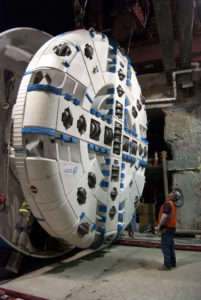
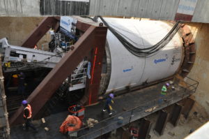
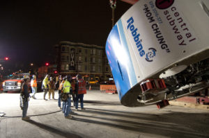 San Francisco’s Central Subway rail tunnels, snaking through downtown areas, were required to be driven below the existing Bay Area Rapid Transit (BART) line. Robbins provided two 6.3 m (20.7 ft) diameter EPBs to bore twin tunnels for the city’s newest rail route. The machines, operated by contractor Barnard/Impregilo/Healy JV, were nicknamed “Mom Chung” and “Big Alma”, after local historical figures.
Geology
Geological testing revealed layers of mixed ground. Two 2.5 km (1.5 mi) long tunnels were excavated through ground ranging from soft soils to thinly bedded siltstone, shale and sandstone bedrock, as well as concrete diaphragm walls. The TBMs were designed with a number of special features to efficiently manage the varied geology, navigate the steep and turning alignment, and bore in what has been rated as “Potentially Gassy with Special Conditions” by Cal/OSHA.
Machine Design and Excavation
 Steering the TBMs accurately through tight curves was one of the key challenges of the project. A mixed face cutterhead was selected and designed to excavate the anticipated wide variety of ground, while active articulation was integrated between the TBM shields to lessen the risks of segment damage, ring deformation, and settlement during boring through curves. Both machines were designed to enable smooth excavation around tight turns with active articulation to excavate curves as small as 137 m (450 ft) in radius. Robbins continuous conveyors offered efficient muck removal throughout tunneling.
Low cover, nearby utilities, and sensitive structures required analyses and design precautions in order to limit settlement impact. This was especially true of a crossing directly below live rail tunnels for the Bay Area Rapid Transit (BART). Compensation grout pipes were put into place as a contingency, but were not needed as the machines passed just 3.4 m (11 ft) below the rail lines with minimal settlement. Careful monitoring of the key TBM parameters ensured that boring did not impact the critical structures over the tunnel that ran through the heart of downtown San Francisco.
Breakthrough
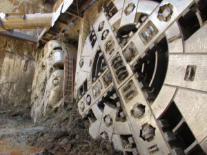 The first of the two machines holed through on June 2, 2014, the second followed close behind and broke through on June 11, marking the completion of the twin tunnels. Both Robbins machines achieved swift advance rates of up to 40 m (131 ft) in 24 hours and 513 m (1,683 ft) in one month.
Jaipur Metro
Twin EPBs Excavate Under Historic Structure
Project Overview
 The city of Jaipur, India is encircled by a wall six meters high and three meters thick, with seven gated openings. It is below these delicate and iconic structures that Jaipur’s first Metro, Line 1, travels. For this project, Contractor Continental Engineering Corporation (CEC) decided to refurbish their two 6.52 m (21.3 ft) diameter Robbins EPBs. The machines bored twin tunnels 2.3 km (1.4 mi) in length, directly beneath the historic Chandpole Gate.
Geology
In this particular project, the geology was not anticipated as a main concern. The bores consist mainly of silty sands, with a minor amount of clay and gravels. However, the geological conditions coupled with the extremely low overburden in the area of the launch shaft, especially the section passing beneath Chandpole gate, was cause for major concern.
The Machines
The contractor opted to refurbish its two 6.52 m (21.3 ft) diameter Robbins EPBs originally used for the New Delhi Metro Project. The Robbins EPBs were refurbished in India, and customized for the Jaipur project. The original machines for New Delhi bored a straight tunnel and did not require active articulation, but a 430 m (1,410 ft) radius curve in Jaipur necessitated that the machines be articulated. The shields were essentially cut in half and another section put in to form articulation joints in the contractor’s casting yard. In addition, new a+b grouting systems were installed as well as sophisticated tunnel guidance systems to monitor each machine’s position.
Boring Below the Historic Chandpole Gate
Chandpole gate, one of the seven, is directly above the bore path for the Line 1 extension, and serves as a historical landmark. The construction materials of the walls and gate consist of irregularly-sized pieces of stone cemented together with lime mortar and faced with a sand and lime mortar render that provide little to no resistance to tunneling-induced settlement. Contractually the allowable limit for surface settlement was set at 4 mm (.16 in). Yet, there was also an Indian archeological law in place that made the stakes a bit higher. It states, “Whoever destroys, injures, mutilates, defaces, alters, removes, disperses, misuses, imperils or allows to fall into decay a protected monument, or removes from a protected monument any sculpture, carving image, bas-relief, inscription or other like object, shall be punishable with imprisonment for a term which may extend to six months with a fine which may extend to five thousand rupees or with both.”
 The key to boring beneath the gate without any adverse effects relied on refining the TBM operating parameters before the TBM reached the zone of influence. As this had been achieved, these parameters were maintained after the restart and similar results were achieved up until ring No. 75, where surface heave increased slightly. Due to the increase in heave the EPB pressure was reduced to 1.2 bar and cutterhead speed to 1.1 RPM. These changes reduced the heave to within tolerance. Although vibrations levels were minimal, as the TBM approached the gate the cutterhead speed was further reduced to 1.0 RPM to reduce the risk of damage by vibration. The machine passed beneath the gate and through the zone of influence without incident using these parameters. The maximum recorded settlement in the vicinity of the gate was 2 mm (.08 in) and absolutely no adverse effects were sustained to the gate. The lessons learned on the first drive were applied to the second drive and TBM II also passed beneath the gate with minimal settlement and no damage to the gate.
Colector-Interceptor superior del Noroeste
Descripción del proyecto
 El interceptor superior Noroeste (UNWI, Upper Northwestern Interceptor), un proyecto colector de aguas residuales en Sacramento, comprende cerca de 30 km de túneles. El proyecto se creó para asegurar que las necesidades de evacuación de agua presentes y futuras queden cubiertas, especialmente ante las grandes tormentas que acaecen durante la estación húmeda que conllevan el riesgo de desborde de las infraestructuras actuales. El proyecto UNWI se dividió en 9 secciones, comenzando la primera en Natomas y terminando la novena en los barrios de Citrus Heights. En 2008 el proyecto había completado todas sus secciones desde la tercera hasta la novena. El sistema está proyectado para transferir hasta 560 millones de litros de agua residual al día.
El 22 de agosto de 2007, la propiedad Sacramento Regional County Sanitation District (SRCSD) adjudicó el contrato de construcción de las secciones 1 y 2 del proyecto UNWI a la UTE de Traylor y Shea por 97,3 millones de Dólares. Traylor/Shea adquirieron una tuneladora Robbins EPB e 4,25 m de diámetro optimizada para los terrenos a perforar, consistentes en arcillas y arenas sueltas.
Tuneladora EPB
La tuneladora Robbins EPB se diseñó con una cabeza de corte de tipo de radios equipada con chapas de acero antidesgaste. La cabeza de corte disponía de orificios para la inyección de espuma de bentonita al frente de excavación para estabilizarlo y propiciar un flujo suave del escombro. Dicho escombro lo recogía un transportador sinfín de eje de 500 mm de diámetro que descargaba en un sistema de cinta continua Robbins. Se utilizó un sistema de inyección bicomponente para estabilizar aún más el terreno detrás de las dovelas de revestimiento, reduciendo de este modo la posibilidad de asentamientos en superficie. La ventaja de la inyección bicomponente es que la mezcla se podía bombear utilizando equipos de bombeo de hormigón estándar en vez de las bombas de alta presión que normalmente se precisan para la inyección de relleno compuesto por un solo líquido. Reduciendo la presión de bombeo se reducía a su vez la probabilidad de añadir tensiones a los suelos a excavar.
La máquina, dotada de sistemas de articulación active, podía negociar curvas de radio tan reducido como 400 m. Se escogió el diseño de articulación activa para que permitiese el giro de los escudos delantero y trasero independientemente de la acción de los cilindros de empuje, eliminando el problema habitual de deformación de anillos en tramos curvos.
Excavación del túnel
 La EPB comenzó a perforar en enero de 2009 desde la nueva estación de bombeo de Natomas. El terreno a perforar por debajo del eje del túnel consistió en su mayoría en arenas, mientras que la parte superior del frente de excavación estaba compuesta de arcillas. La solera del túnel venía a situarse entre 7 y 14 m bajo la superficie, con presencia de agua a lo largo de toda la perforación.
Para acortar los plazos de construcción, Traylor/Shea y la propiedad SRCSD diseñaron un sistema de revestimiento del túnel nunca utilizado con anterioridad en los EEUU. Las dovelas prefabricadas de hormigón, de 228 mm de espesor se protegieron con láminas de PVC de 1,8 mm. El revestimiento de PVC protege al hormigón del deterioro producido por gases emanados de las aguas residuales, con el resultado final de evitar la instalación de una tubería de transporte y la terminación del túnel inmediatamente operativo con la instalación de las dovelas revestidas, reduciendo el tiempo de puesta en servicio del colector.
Traylor/Shea también decidió utilizar Cintas continuas para la evacuación el escombro dado que en la mayor parte de las ocasiones incrementan la eficacia, su inicio de operación es más sencillo y presentan una mayor disponibilidad que el sistema tradicional de vagones de escombro. El sistema de cinta se diseñó para acomodarlo a las diferentes condiciones de terreno a encontrar en sus 5,7 km de longitud. Entre sus características destacamos los puntos de descarga y tolvas de recepción sellados con uretano y goma para minimizar derrames de material. La espuma y los aditivos bentoníticos ayudaron a mantener una consistencia del escombro que le permitía fluir suavemente hacia las cintas incluso ante la presencia significativa de aguas subterráneas.
La máquina obtuvo en su recorrido algunos de los más altos índices de avance en terreno blando, consiguiendo repetidamente rendimientos de 210 m/semana y 50 m/día, en tres turnos de ocho horas. Además, el sistema de cintas continuas funcionó con una disponibilidad de más del 90% durante toda la obra. La perforación terminó el 21 de noviembre de 2009 cuando la EPB Robbins caló el túnel con dos meses de adelanto sobre la fecha prevista.
Guangzhou Metro, GuangFo Line
Descripción del proyecto
 Desde el año 2006, China ha invertido cerca de 200.000 millones de Dólares en infraestructura ferroviaria, en lo que se prevé que sea el mayor proyecto de expansión nacional de una red ferroviaria desde el que se acometió en los EEUU en el siglo XIX. La prolongación del metro de Guangzhou es parte del proyecto de ferrocarril de alta velocidad entre ciudades del delta del río Perla y representa el primer enlace ferroviario de alta velocidad entre dos ciudades chinas. La línea GuangFo, entre Guangzhou y Foshan, de 32,2 km de longitud, se adjudicó dividida en 12 lotes en los que la propiedad, la Guangzhou Metro Company, ha decidido emplear 16 tuneladoras para su excavación.
El Lote 12 del proyecto, que comprende el tramo entre las estaciones de Jushu, Xilang, y Hedong, se adjudicó en 2007 al contratista China Communication Construction Corp., 2nd Navigation Engineering Bureau Ltd. (CCCC). Dicha empresa adjudicó a Robbins el suministro de dos tuneladoras EPB de 6,3 m de diámetro para perforar los dos túneles paralelos de 2600 m de longitud. Las tuneladoras arrancaron respectivamente en enero y febrero de 2009 desde la estación de Jushu al sur de Guangzhou.
Geología
Los terrenos a atravesar en la perforación del lote 12 del proyecto consistieron en perfiles complejos y estratificados conteniendo granitos en todos sus grados de meteorización, arenas compactas y limos a presiones de hasta 4 bar. Cerca del 70% de la perforación se realizó en frente mixto, con terrenos blandos en la mitad superior del frente y roca de hasta 50 MPa en la inferior. El 30% restante consistió en arenas fluyentes con altos contenidos en agua.
Tuneladoras EPB
Ambas tuneladoras EPB se equiparon con cabezas de corte de tipo de radios con porcentaje de apertura de hasta el 37%, permitiendo el flujo suave de escombro a la cámara de mezcla. Para perforar los terrenos mixtos descritos, las cabezas contaron con cortadores de disco de 17” y con cortadores de botones de carburo de tungsteno.
Las cabezas de corte contaban con cuatro puntos independientes de inyección de espuma al frente para su consolidación, reduciendo los requisitos de par de la máquina. Se evacuó el escombro mediante un transportador sinfín de tipo de eje y de 800 mm de diámetro, ya que no se preveía el ingreso de bloques grandes de roca en la cabeza. La máquina se diseñó con una articulación activa debido a las curvas contenidas en la alineación del túnel, con radios tan pequeños como 200 m.
Excavación del túnel
 En sus primeros siete meses de perforación, las dos máquinas obtuvieron nada menos que 16 récords del proyecto completo, incluyendo un mejor mes de 377 m que superó el rendimiento de cualquiera de las 16 tuneladoras participantes en la línea de GuangFo.
Uno de los mayores retos del proyecto fue el control de los asentamientos del terreno, dado que los túneles discurrían bajo ríos, carreteras y cimentaciones de edificios muy vulnerables. Los anillos de dovelas, de 300 mm de espesor, se inyectaron con mortero. Entre las zonas de alto riesgo de asentamiento destacamos el paso bajo el río Huadi, de 80 m de anchura y solo 4 de profundidad, entre las estaciones de Jushu y Xilang, así como las piscifactorías experimentales del río Perla, bajo cuyos estanques discurrió el túnel.
Ambas máquinas finalizaron sus trabajos con un mes de Adelanto al plan previsto y obtuvieron rangos de disponibilidad del 95%. Hasta agosto de 2009 solo se habían cambiado 66 cortadores de disco en la primera máquina y 46 en la segunda. No hubo necesidad de reemplazar ninguno de los cortadores de botones en todo el proyecto. La primera máquina caló en la estación de Xilang el 15 de agosto de 2009 mientras que la segunda lo hizo en septiembre, teniendo lugar los cales definitivos en septiembre y octubre de 2009 respectivamente.
Prolongación del metro de Nueva Delhi
Descripción del proyecto
 El ambicioso proyecto de la Fase II de la prolongación del metro de Nueva Delhi prevé la construcción de 53 km de línea nueva al objeto de reducir los tiempos de tránsito, apuntando en particular a la celebración de los Juegos de la Commonwealth en la ciudad en el año de 2010. La propiedad del proyecto, Delhi Metro Rail Corporation (DMRC) terminó en noviembre de 2006 la Fase I del proyecto, consistente en la construcción de 65 km de línea nueva incluyendo 59 estaciones. Esta nueva Fase II, con un presupuesto de 1800 millones de USD precisa de la perforación de varios túneles en terreno blando por tuneladoras EPB, que enlazarán las estaciones construidas previamente en zanja.
El 1 de febrero de 2007, Robbins y Mitsubishi Heavy Industries (MHI) firmaron un contrato con la agrupación CEC/Soma para el suministro de dos tuneladoras EPB de 6,5 m de diámetro, con sus correspondientes equipos de rezaga y herramientas de corte. Robbins construyó las máquinas con componentes fabricados en los EEUU, India y China.
La primera de las dos TBMs arrancó el 15 de mayo de 2008 en un pozo de 18 m de profundidad en la estación de Jor Bagh. Las máquinas debían perforar túneles paralelos de 2 km de longitud conectando las zonas de Udyog Bhawan y Green Park de Nueva Delhi, como parte del contrato BC-16. La segunda máquina arrancó en el mismo punto en la última semana de junio de 2008.
Geología
Los túneles discurrieron entre 8,6 y 14 m por debajo del nivel freático, atravesando formaciones de limo arenoso, arena limosa y gravas.
Diseño de las máquinas
Las cabezas de corte de ambas EPBs se diseñaron con un 55% de superficie abierta para permitir un caudal suave de escombro y evitar los atascos en las mismas. Las máquinas emplearon diversos tipos de picas de carburo de tungsteno para excavar un material tan blando como abrasivo y de alto contenido en agua, que era evacuado a través de un transportador sinfín de tipo de eje. El revestimiento del túnel se erigía de modo continuo y consistía en anillos de dovelas de hormigón armado de 275 mm de espesor.
Excavación del túnel
 El 29 de septiembre de 2008, la primera de las tuneladoras Robbins completó su primer tramo de excavación de 1 km calando en la estación de Race Course. Los altos índices de avance obtenidos, de 19 anillos instalados al día, junto con la disponibilidad de la máquina. Que se elevó hasta un 90% de media, fueron factores clave en la rapidez con la que se terminó la perforación. La máquina se desmontó en un foso y se transportó por carretera hasta el extreme opuesto de la estación de Race Course a 310 m de distancia, desde donde comenzó la segunda parte de su cometido excavando hasta la estación de Udyog Bhawan. En este tramo la máquina alcanzó un récord de proyecto de 168 anillos instalados en una semana, por encima del rendimiento de cualquiera de la s otras 14 tuneladoras participantes en el proyecto.
Para el mes de abril de 2009, los tramos previstos para perforar con las EPBs Robbins estaban terminados por lo que uno de los contratistas, CEC pudo utilizar una de las máquinas para perforar 567 m de túnel entre las estaciones de AIIMS y Green Park, terminándolo el 14 de julio de 2009.
Línea 12 del Metro de México D.F.
Descripción del proyecto

El sistema de Metro de México D.F. es uno de los más extensos del mundo, con más de 200 km de vía instalada y transportando a cerca de 4 millones de pasajeros al día. La nueva línea, de 25,4 km de longitud, atraviesa 22 estaciones nuevas entre los barrios de Tlahuac y Mixcoac. El nuevo túnel de 7.7 km representa la primera nueva ruta en la capital en más de diez años y dará servicio a miles de pasajeros diariamente.
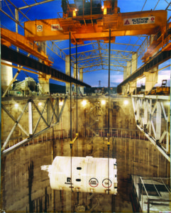
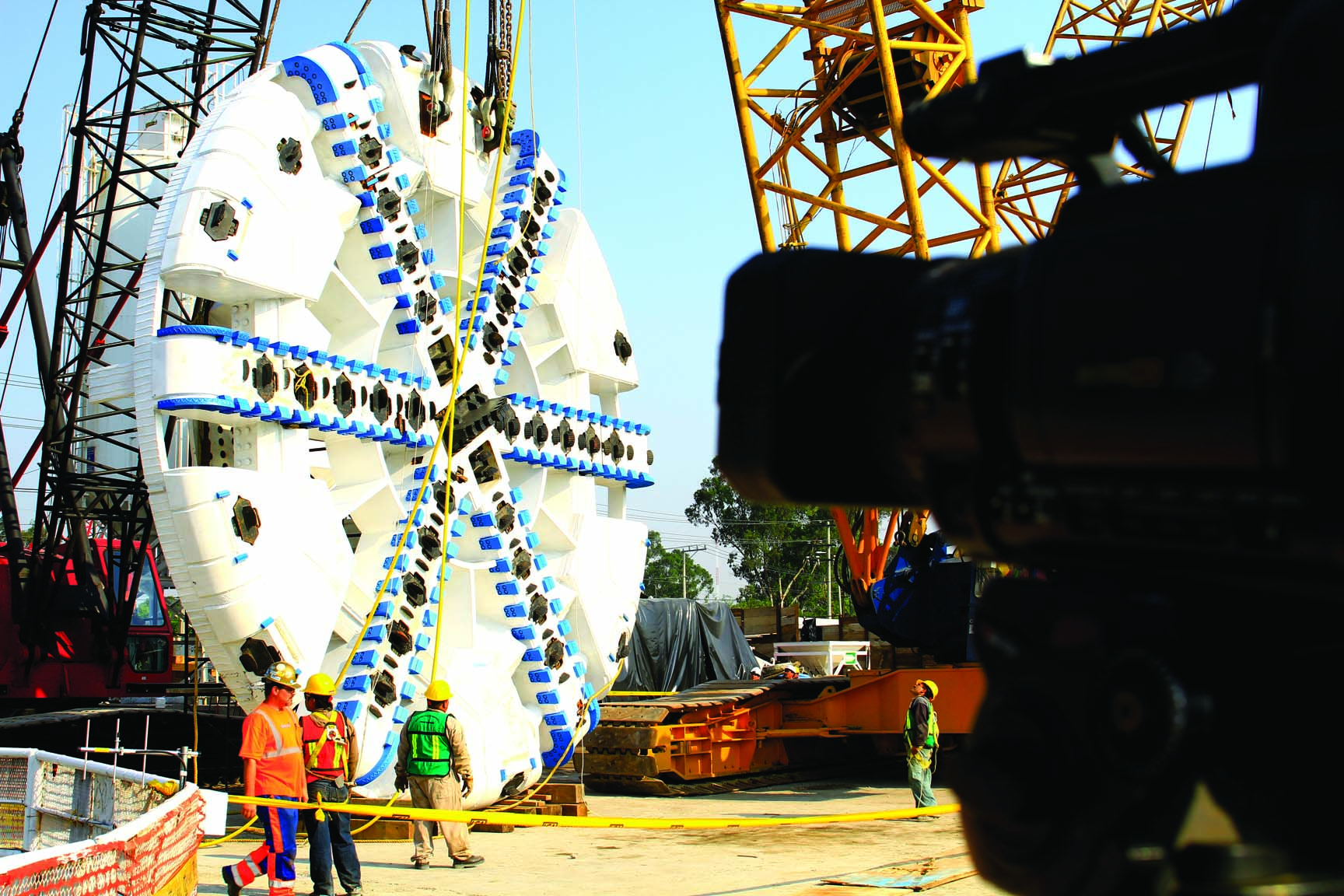
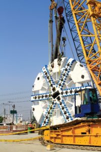
En 2007, el Distrito Federal hizo público su plan de construir la línea 12 del metro de México D.F. El Consorcio ICA, adjudicatario de la obras, encargó a Robbins la fabricación de una tuneladora EPB de 10,2 m de diámetro, de su back-up y de las herramientas de corte necesarias. La TBM es la más grande que ha trabajado nunca en México y fue la primera tuneladora en la historia de Robbins que se acogió al plan de Primer Montaje en Obra (OFTA, en siglas inglesas). La geología a atravesar en esta línea de metro consiste en capas de arcillas, arena y bolos rocosos de hasta 800 mm de diámetro, dado que la zona corresponde a parte del antiguo lecho de un lago. Las condiciones de terreno bajo México D.F. son verdaderamente especiales y se precisó un programa muy detallado de control de las vibraciones debidas a la perforación.
La gigantesca tuneladora va equipada con un transportador de tornillo sinfín de tipo de guirnalda, de dos etapas, 1200 mm de diámetro, seguido por otro sinfín de tipo de eje, especialmente diseñados para gestionar la evacuación e bolos rocosos de gran tamaño. En ciertas zonas del túnel en las que se atravesaban arcillas muy blandas con alto contenido en agua, el escombro se evacuó utilizando bombas de lodos, en lugar de cintas o vagones de escombro. La máquina también disponía de articulación active para evitar las deformaciones de los anillos de dovelas instalados en curvas tan cerradas como de 250 m de radio. La cabeza de corte, de tipo de brazos radiales, llevaba útiles de corte afilados de carburo de tungsteno para mayor eficacia en el corte de terrenos blandos. Los asentamientos del terreno se controlaron mediante el uso de aditivos y de inyecciones de dos líquidos en el trasdós de las dovelas. Las inyecciones de dos líquidos, cemento y acelerante, se endurecen con rapidez y eliminan la necesidad de usar bombas de hormigón de alta presión que pueden ocasionar perturbaciones al terreno. La máquina revestía el túnel mientras avanzaba, instalando un anillo universal de 7+1 dovelas de 400 mm de espesor.
La EPB Robbins arrancó el 15 de febrero de 2010 tras solamente ocho semanas de montaje. El pozo de ataque, de unos 34 m de longitud, 14 de anchura y 17 de profundidad, estaba situado en una de las zonas más densamente pobladas de la ciudad. Dadas las pequeñas dimensiones del pozo, la máquina perforó sus primeros 70 m accionada remotamente desde los remolques del back-up todavía en superficie. Los remolques se fueron arriando y añadiendo al equipo según la máquina avanzaba.
 La mayor parte del túnel discurrió bajo coberturas tan escasas como 7,5 m, por lo que se precisó un control muy fino de los asentamientos del terreno. La situación del túnel en pleno centro urbano implicaba la proximidad de un buen número de estructuras de construcción anterior. La máquina pasó a solo 1,5 m de un colector de 4 m de diámetro, a 2 m de cimentaciones de edificios y a únicamente 3,5 m por debajo de las líneas activas de metro 2 y 3. La máquina alcanzó su primera estación en abril de 2010 tras perforar 495 m de túnel. Las mayores dificultades se encontraron en las tuberías de lodos pero, después de ser rediseñado, el sistema funcionó de manera excepcionalmente buena. Desde ese punto, la EPB atravesó seis estaciones más en cada una de las cuales se le practicó un mantenimiento rutinario. El 1 de marzo de 2012 la máquina complete con éxito la totalidad del túnel.
A su terminación, la línea 12 del metro de México D.F. es la más larga de todo el sistema. Esta nueva línea se estima que transportará una media de 367.000 pasajeros al día, alcanzando así el cuarto lugar en cuanto a las rutas de tránsito sobre vía más frecuentadas en la capital.
The Channel Tunnel
Project Overview
 The Channel Tunnel, one of the world’s most famous tunnels, is a 50 km (31 mi) tunnel under the English Channel linking Great Britain to France. This link consists of three parallel tunnels running for 39 km (24.2 mi) under the sea. Two Main Rail Tunnels, about 30 m (98 ft) apart, carry trains from the north and from the south. In between the two tunnels is the Channel Service Tunnel, which is connected by cross-passages to the main tunnels. This service tunnel allows maintenance workers to access the rail tunnels at regular intervals.
The contractor for the project, Transmanche-Link (TML) chose five Robbins TBMs to participate in boring the crossings. TBMs were deployed at both the U.K. and France Terminals.
Geology
The majority of the Channel Tunnel passes through chalk marl, much of it faulted. Below the Chalk Marl is a thin 2 m (6.5 ft) band of permeable Glauconitic Marl. This rock is a weak sandstone with a stronger rock strength than the Chalk. The bottom of the tunnels pass through stiff clay with some swelling characteristics. The Chalk is much more faulted and prone to water inflows on the French side of the tunnels.
TBMs
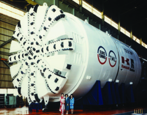 Robbins built five machines for this project, each designed for the geology of a specific length of tunnel.
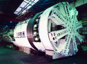
The high water pressures predicted in the folded and faulted chalk on the French side required the use of three Earth Pressure Balance machines (EPBMs). These machines featured sealed cutter chambers to withstand high water pressures and screw conveyors to carry the cut material from the face.
Robbins built two EPBMs for the French side of each Main Rail Tunnel. These 1,100 tonne (1,200 ton), 8.8 m (29 ft) diameter machines had a cutterhead thrust of 19,613 kN (4,413,000 lb) and generated a maximum torque of 12,748,645 N-m (9,410,000 lb-ft).
The undersea French side of the Channel Service Tunnel also required an EPBM. This machine featured a 5.6 m (18 ft) diameter cutterhead, a cutterhead thrust of 39,227 kN (8,837,000 lb), and a maximum torque of 3,510,781 N-m (2,591,000 lb-ft).
Two Double Shield TBMs were built for the U.K. terminal because fewer water inflows were predicted. Robbins designed these machines to withstand unstable and faulted rock conditions. The 8.36m (27 ft) diameter machines included 13 inch (330 mm) cutters and 65,871 kN (14,821,000 lb) of thrust. The machines generated a maximum 5,727,084 N-m (4,227,660 lb-ft) of torque.
Tunnel Excavation
 Machines were deployed on both sides of the tunnels in December 1987. The three French seaward TBMs encountered water inflows almost immediately, forcing the use of the sealed mode of operation much earlier than anticipated. The sealed cutterheads of the machines could withstand 10 bar (145 psi) of water pressure; however, additional measures were required to seal the remainder of the machines against water inflow.
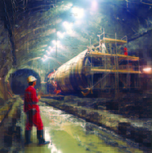
The tail shields of the TBMs were fitted with multiple rows of wire brush seals that pressed against the outside diameter of the concrete segment lining. Grease was injected into wire brushes and the 100 mm (4 in) space between the metallic brushes and the tunnel lining. Grout lines were fitted into the tail shield allowing fine cement grout to be injected into the 152 mm (6 in) annulus between the tunnel lining and the ground. This method sealed the tunnel lining as the TBMs advanced. In spite of the difficult conditions, advance rates improved throughout the boring with the Robbins service tunnel machine averaging 714 m (2,342 ft) per month for the project.
The U.K. machines also experienced some difficult tunneling conditions at the outset. Unforeseen water inflows in a 3.2 km (2.0 mi) stretch caused the machines to slow their progress as each section of tunnel had to be grouted in advance of boring. After passing through this section of tunnel, the machines experienced no further difficulties and began averaging 149 m (490 ft) a week. The Robbins machines on the U.K. side averaged 873 m (2,864 ft) per month and set world records for a best day of 75.5 m (247.7 ft), a best week of 428 m (1,404 ft), and a best month of 1,719 m (5,640 ft) — all of which have yet to be beaten.
 Muck transport on both sides of the tunnel was complicated but worked well. In the U.K. a rail system of 500 muck cars transported muck back to the access adit at Lower Shakespeare Cliff and fed it onto a high-speed conveyor. The conveyor then dumped the muck into lagoons behind sea walls in the English Channel. In all, about 4 million m3 (5.23 million cubic yards) of chalk were dumped at the site. The area, called Samphire Hoe, is now a popular park.
On the French side muck was crushed and mixed with water in a chamber at the bottom of the Sangette access shaft. It was then pumped up the shaft and behind a 30.5m (100 ft) dammed reservoir.
 In December 1990, the French and British TBMs met in the middle and completed the Channel Service Tunnel bore. In all of the tunnels the French TBM was dismantled while the U.K. TBM was turned aside and buried.
The Main Rail Tunnels met on May 22, 1991 and June 28, 1991. Both accomplishments were celebrated with breakthrough ceremonies to commemorate the building of one of the world’s longest and most ambitious undersea tunnels.
Tampa Bay
Descripción del proyecto
 El túnel de South Central Hillsborough discurre bajo el río Alafia en la bahía de Tampa. El túnel es parte de la etapa B del Plan Maestro de Aguas, un ambicioso programa en tres etapas para reaprovisionar los empobrecidos depósitos de aguas subterráneas de Florida.
La propietaria del proyecto, Tampa Bay Water, adjudicó el contrato nº 2 del túnel de South Central a Kenko Inc. en 2002. El contratista eligió una solución innovadora para abordar las difíciles condiciones geotécnicas del proyecto: una tuneladora Robbins EPB híbrida.
Geología
El túnel atraviesa las extremadamente permeables calizas del acuífero de Florida que se presentan muy fracturadas, teniendo la tuneladora que afrontar presiones hidráulicas en el frente de hasta 2,5 bar. Por encima de la caliza existe una capa muy rígida de arcilla verde y, por encima de ella, una capa superficial de unos 4 m de espesor de arena fina, suelta y limosa.
EPBM
El contratista del proyecto seleccionó a Robbins como proveedor ya que necesitaba un diseño que englobase características de tuneladoras de roca dura, EPBs y escudos de lodos (“slurry”). La tuneladora Robbins montaba ocho cortadores dobles y cuatro sencillos de 17”, desmontables desde el interior de la máquina. La máquina era capaz de proporcionar un empuje de 5783 kN y un par en la cabeza de 409457 Nm.
La cabeza de corte llevaba dos aberturas, una a cada lado de la máquina, a través de las que se podía perforar para sondeos o inyectar productos ante condiciones de terreno poco competente. Un transportador sinfín de 432 mm de diámetro recogía los escombros en la solera del túnel, que después se transportaban a una mezcladora donde se machacaban los escombros calizos. El sistema completo de excavación era cerrado y de frente presurizado para soportar la presión hidráulica de hasta 3 bar.
El escombro se trasvasaba desde la mezcladora hasta una bomba de lodos instalada en el interior del túnel que lo enviaba a través de una tubería al pozo de arranque desde donde una segunda bomba lo llevaba hasta la superficie. Esto era debido a que las calizas eran tan porosas que no podían formar una matriz competente, siendo el escombro resultante muy difícil de trasvasar a vagones desde el transportador sinfín.
Excavación del túnel
 La tuneladora EPB híbrida comenzó a trabajar el 27 de mayo de 2002. En sus primeras etapas funcionó como EPB pura, evacuándose los escombros mediante vagones.
A medida que avanzaba, la tuneladora se vio sometida a cargas hidráulicas cada vez mayores hasta alcanzar los 2,5 bar. En esta situación, según lo previsto, se instaló un sistema de sujeción de la máquina circular, para mantenerla en posición.
E-n esta situación, las altas presiones de agua impedían el manejo del escombro líquido de manera eficaz entre el transportador sinfín y los vagones y los aditivos inyectados al terreno no surtieron el efecto deseado, continuando la entrada de agua al túnel. Entonces fue cuando se transformó el sistema de gestión del escombro comenzándose a utilizar las bombas de lodos.
Tras la modificación, la máquina progresó de manera adecuada y caló el túnel el 22 de agosto de 2002 con una desviación de únicamente 3 mm sobre su objetivo geométrico.
Chengdu Metro Line 2 Lot 18
Robbins EPB sets Record Rates in Chengdu
Project Overview
 Chengdu’s Metro Line 2 includes 26 stations and 17.6 km (10.9 mi) of tunnels between Longquandong and Shiniu areas of the city. Seven lines totaling 274 km (170 mi) are planned to be operational by 2035, and will service 13.1 million daily passengers.
The contractor, CRCC Bureau 23, selected a Robbins EPB with a mixed ground cutterhead for the potentially variable conditions, as well as the back-up system, soft ground cutting tools and spares. The machine was launched in January 2010 to bore two 1.4 km (0.9 mi) sections of parallel tunnel, with a breakthrough at the midway point into an intermediate station. The tunnel alignment allowed the machine to pass 25 m (82 ft) below residential buildings, and included several curves with a minimum 400 m (1,300 ft) radius.
Geology
The tunnels for Lot 18 of Line 2 are located in highly variable, permeable alluvium, stiff sand, and clay, requiring a unique EPB TBM design and careful monitoring for settlement. This complex alluvial geology is unlike that found anywhere else in China. Cobbles averaging from 20 to 80 mm (0.8 to 3.1 in) in diameter were predicted, with diameters of as much as 120 mm (4.7 in) possible.
Machine Design
The mixed ground, spoke type cutterhead was mounted with Tungsten carbide knife-edge bits and seven 17-inch (432 mm) diameter disc cutters around the gauge. A foam injection system was used to stabilize the running ground, allowing each cubic meter of foam mixture to stabilize about 40 rings of ground. Subsidence was intensively monitored and crews were trained to utilize probe drilling and ground consolidation if settlement was detected. Variable frequency (VFD) drives allowed the cutterhead rotation to be kept low (around 1.5 RPM at maximum) to also minimize surface settlement. High advance rates were instead achieved using increased cutterhead torque, which results in a faster rate of penetration. One-liquid type back-filling grout was used to fill the gap between segment lining which consisted of 300 mm (12 in) thick reinforced concrete segments set in a 5+1 arrangement.
Tunnel Excavation
 In June 2010, the machine had broken through into the intermediate station, approximately 1,397 m (4,583 ft) into the 2.7 km (1.6 mi) long tunnel. Following scheduled maintenance, the machine was relaunched to bore the remaining section of the tunnel. Cutter wear was very minimal, with only three cutters changed since the start of boring.
By the time of tunnel completion in December 2010, the machine had achieved a project landmark of 129 m (423 ft) in one week, and 459.5 m (1,507 ft) in one month – higher rates than at least 4 other machines working on Line 2 in similar geology.
Emisor Oriente
Three Robbins EPBs bore Vital Wastewater Tunnel in Mexico
Project Overview
 In an urgent effort to prevent flooding in the urban capital of Mexico City, the National Water Commission (CONAGUA) has ordered the construction of a 62 km (39 mi) long wastewater line, Emisor Oriente, which is expected to help increase Mexico City’s wastewater capacity and ease some of the city’s related problems. Torrential rains and continuing floods in Mexico’s capital during the rainy season have increased the urgency of the job, quickly making it the country’s most critical infrastructure project.
The Emisor Oriente project was divided into six lots – Lots 1, 2 and 5 awarded to Mexican contractor Ingenieros Civiles Asociados (ICA), S.A. de C.V., Lots 3 and 4 to Carso Infraestructura y Construcción, S.A. de C.V., and Lot 6 to Lombardo Construcciones and Constructora Estrella. Three 8.93 m (29.3 ft) Robbins Earth Pressure Balance Machines (EPBs) are excavating Lots 1, 3, 4, and 5 of the tunnel.
Geology
Mexico City is located in the Valley of Mexico. The area contains an ancient, drained lake bed and is surrounded by volcanic mountain ranges. The soil is mainly made up of watery clays running up to 80 m (263 ft) deep with the water table just 2 to 3 m (6.6 to 9.8 ft) below the surface. The ground also contains boulders up to 600 mm (24 in) in diameter. Due to the complex ground conditions, engineers believed for years that the ground would be too difficult to excavate. Despite the challenging terrain, Mexico City’s main wastewater line, Emisor Central, was hand-mined in 1964 approximately 100 m (328 ft) below ground, paving the path for future underground construction projects.
Equipment Features
The Robbins EPBs were designed for the particularly difficult ground conditions they would be facing on the job site. Although difficult ground was anticipated, shaft excavations in 2009 and 2010 revealed much more complex terrain than originally expected, resulting in various modifications on each machine. The EPBs were built with mixed-ground, back-loading cutterheads with carbide cutter bits to deal with variable ground conditions, and ribbon-type screw conveyors to remove large boulders. Redesigned pressure bulkheads were added to the machines to accommodate the higher water pressures of the region, and enhanced wear detection was added to the cutter bits to ensure optimal performance. Robbins continuous conveyors are being used behind each machine in order to quickly remove muck from the jobsite and minimize downtime. Each continuous conveyor system and vertical belt is installed once the machines have bored ahead 150 m (492 ft) from their launch points.
Excavation
One Robbins EPB was launched for Lot 1 on July 13, 2011 – a change from its originally scheduled tunnel drive at Lot 5. A flood at Lot 1 delayed the Herrenknecht machine that was originally designated to bore the area for six months, prompting the contractor to begin boring with the Robbins EPB. The machine started excavation at shaft 5 of Lot 1 using umbilical cables connected to the surface and a sludge pump for muck removal.
Excavation at Lot 1 was fast-tracked because of problems with Mexico City’s main open sewer line, the Gran Canal. The canal was constructed in 1910 and floods its banks on a regular basis, causing road closures and significant health problems to the city’s residents. The canal has a positive vertical alignment, resulting in potentially large volumes of water that could overload current pumping stations and send untreated water back into the city. The canal’s slope loss is due to the area’s sinking lake clays. To help remedy this problem, a treatment plant and pumping station are being constructed in shaft 5 of Lot 1 so water diverted from the section of the Gran Canal to Emisor Oriente can be pumped back into the Gran Canal where the slope has not been compromised. Although there were many challenges the first EPB machine had faced, it was able to make a successful breakthrough 15 months later. Once the Robbins EPB had bored its 4.6 km (2.9 mi) drive to shaft 3A of Lot 1, it was dismantled, removed, reassembled at Lot 5, and began boring its original 8.6 km (5.3 mi) long bore in early 2014.
 The remaining two Robbins EPBs started excavation in 2012, working on 9.2 km (5.7 mi) and 10.2 km (6.3 mi) drives at Lots 3 and 4, respectively. Once excavation was initiated, the machines quickly encountered sections of abrasive basalt rock and ash, boulders and blocky ground that wore on cutting tools and the cutterhead. As a result, the harsh ground conditions led to accelerated wear and damage on some of the cutting tools as well as the screw conveyors.
In efforts to manage the sudden impact of the challenges faced and to maintain control of the situation, the operational parameters at Lots 3 and 4 became a high priority. Improvements to the cutter change time on the central disc cutters were made possible with the design of a new rotary union. To reduce the abrasive wear on the cutterhead, more durable face and gauge scrapers were added to the cutterhead.
The Lot 3 machine underwent additional changes after boring 2.7km (1.6 mi) of its tunnel. The machine was given a new cutterhead fitted with chromium carbide wear plates and smaller openings to reduce blockages. The machine also get a new screw conveyor design with special wear plates, and a reinforced casing with additional gates and injection ports.
At Lot 4, the other Robbins Machine has fared better in soft rock, despite having a lot of water pressure to deal with—the machine even holds the shift record for the project, of 28 rings.
 The Lot 5 Robbins machine, which came from Lot 1, needed major modifications before starting at Lot 5 to help deal with expected water pressures up to 7 bar. The TBM—launched from the deepest shaft at a civil works project in Mexico (150 m)—was fitted with new hyperbaric chambers, as well as a new gantry for the compressors and air tanks. To speed up disc changes at the center of the cutterhead, the rotary union was also modified.
Project Completion
On May 23, 2019, the last of the six 8.93 m EPBs completed tunneling at Lot 4 of Emisor Oriente, thus ending a ten year campaign of nearly 63 km of tunneling in some of the most arduous conditions crews have ever come across.
With the tunneling complete, the secondary lining operation also had to take place from the various headings using telescopic forms. The tunnel was opened for use in December 2019.
- Cooperative Innovation at the Manhattan Tunnel Project: Digger Shields with Expandable Segments to Excavate Complex Fill
- Robbins celebrates TBM acceptance for Ellicott City North Tunnel
- Huge Robbins Slurry TBM breaks through in Hiroshima
- Robbins TBMs break through at Delhi Metro DC-07 Project
- RETC 2025