 Close
Close  Menu
Menu 
Project Categories: Main Beam TBM
Mumbai Water Tunnel
A National Record in Urban, Hard Rock Conditions
Project Overview
 The Mumbai Water Supply Tunnel runs between the Kapurbawdi and Bhandup areas. The tunnel provides the city’s approximately 20.5 million residents with a reliable water supply, even during the seasonal monsoons that regularly contaminate Mumbai’s water resources. The basalt rock tunnel alleviates Mumbai’s current leakage problems from its aging lines and provide inhabitants with a consistent flow of clean drinking water.
Geology
Abrasive basalt rock and some fractured ground with potential for water inflows.
Onsite First Time Assembly
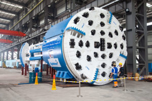
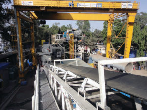
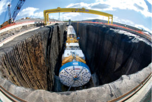
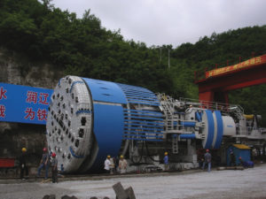
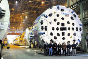
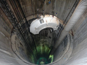 Onsite First Time Assembly (OFTA) was used to assemble the main bearing, lube system, back-up decks and horizontal, vertical and stacker conveyors. OFTA saved the contractor both time and money by assembling the parts at the jobsite and eliminating pre-assembly at the manufacturing facility in Shanghai, China. The OFTA process took place at the shaft bottom in a 100 m (328 ft) long starter chamber and a 50 m (164 ft) long tail tunnel. TBM components were lowered into the shaft using mobile and gantry cranes.
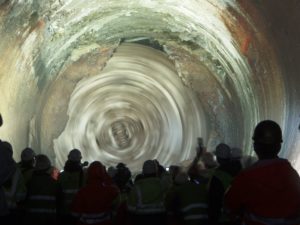
Excavation and Breakthrough
Due to the urban location of the tunnel, the TBM was launched from a 109 m (357 ft) deep shaft, and its launching sequence included an initial start-up excavation of 50 m (164 ft) with vital back-up decks connected to the TBM using cables. The first bore began March 30, 2012 and upon completion, the decks were lowered and a continuous conveyor system was installed for muck haulage and storage.
Robbins provided both the TBM and conveyor system for the project, as well as Field Service personnel to monitor the equipment and assist with daily upkeep and inspection.
 Although the machine was ultimately a success, it did experience its fair share of challenges during the 21-month bore. Difficult ground, including basalt rock, fractured ground, and water inflows, was encountered throughout the tunnel. The tunnel team took all precautionary measures and advanced slowly. The crew maintained good ventilation throughout execution and utilized consistent dewatering to deal with water inflows.
Ground support also played a critical role in poor ground: The rock support system and ring beam erector reduced downtime and stabilized rock. Challenging ground conditions, combined with the sheer depth of the 109 m (357 ft) tunnel, made the machine’s excellent advance rates a particular achievement.
By the end of TBM tunneling, the Robbins machine had reached high rates of 870 m (2,855 ft) per month and 58 m (188 ft) per day, both records for TBM tunneling in India. The contractor stated that the good rates were achieved because of “good performance of the machine and a conveyor system for muck haulage in place of conventional methods.”
West Qinling Rail Tunnels
Twin TBMs set World Records under High Cover
Project Overview
 The West Qinling tunnels are part of the Chinese Government’s Lanzhou to Chongqing Railway, a massive 820 km (500 mi) long scheme that links the capital of Gansu Province (Lanzhou) with southwestern Chongqing, a mega-city of over 35 million people. The parallel rail tunnels are for freight, and link the city of Longnan with the towns of Waina, Luotang and Fengxiang within Gansu Province. The new railway, at a cost of USD $11.3 billion, shortens transport times from 17.5 hours to 6.5 hours and enables an annual freight capacity of 100 million metric tons (110 million US tons). Trains run on the double track lines at 160 km per hour (100 mph), with a 50-train daily maximum.
In January 2009, China Railways signed a contract with Robbins for the supply of twin 10.2 m (33.5 ft) diameter Main Beam machines. The TBMs would be used to excavate two 16.6 km (10.3 mi) tunnels through the Qinling Mountains.
Geology
Geology in the two tunnels consisted of 30 to 80 MPa (4,300 to 11,600 psi) UCS sandstone and phyllite rock beneath more than 1,400 m (4,600 ft) of cover. The corresponding ground support program consisted of continuous mesh and rock bolts, with either ring beams or steel straps, for the length of the tunnel. Rather than roof shield fingers, protected mesh windows were used to install ground support immediately behind the cutterhead. In the event that extremely poor ground was encountered, the mesh pockets could be easily modified to use the McNally Support System, patented by C&M McNally Engineering of Toronto, Ontario, Canada for exclusive use with Robbins TBMs. The McNally System utilizes steel or wood slats to provide continuous support along the roof area of the tunnel, protecting workers from falling rock.
Main Beam TBMs

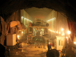
The two machines, for contractor China Railways 18th Bureau (Group) Co., were assembled at a local workshop and transported to the jobsites, where they were assembled on bridges spanning a deep valley. The first machine, for the Left Line, was launched at the end of June 2010 after being walked through a 2.0 km (1.2 mi) long adit tunnel. The second machine, for the Right Line, was launched on July 17, 2010. The TBM tunnels were just 40 m (130 ft) apart and located approximately 1,000 m (3,280 ft) above sea level, about halfway up Qinling Mountain.
Tunnel Excavation
The two Robbins TBMs advanced at world record rates in exceedingly difficult conditions. The first Main Beam Machine advanced 235 m (771 ft) in one week and 841.8 m (2,761 ft) in one month during Spring 2011 – rates much higher than any ever recorded for TBMs in the 10 to 11 m diameter range. The fast advancing Left Line machine also broke through into an intermediate adit tunnel on May 28, 2011 at the 5.5 km (3.4 mi) mark, where it underwent planned maintenance and inspection. Within several weeks the machine was launched again to bore the rest of its tunnel.
 Despite the conditions of phyllite and limestone with high quartz content, only about 100 cutters were changed on the Left Line TBM. The Right Line machine, launched a month later and about 1,000 m (3,280 ft) behind, also experienced good cutter wear. By 2013, both machines had made their final breakthroughs in their respected tunnels.
Proyecto hidroeléctrico Svartisen
Descripción del proyecto
 El 99% de la producción de energía en Noruega procede de centales hidroeléctricas, lo que hace que estos grandes proyectos sean un apieza clave de la infraestructura del país. Este uso tan extenso de energía hidroeléctrica comenzó en 1877, cuando se terminó con éxito su primer proyecto de este tipo. En 1990, Noruega contaba con más de 170 instalaciones hidroeléctricas subterráneas, con aproximadamente 3500 km de túneles y galerías situadas por todo el país. La empresa gestora Statkraft proyecta, construye y opera todas las centrales hidroeléctricas propiedad del gobierno, lo que representa un 28% de la producción total noruega de energía hidroeléctrica. El proyecto Svartisen, situado un poco al norte del círculo polar ártico, consiste en 46 pozos conectados a 40 km de túneles de diámetros entre 3,5 y 5 m. Los túneles están diseñados para recoger y transportar el agua de las montañas glaciares de Trollberget hasta el lago de Storglomvatnet, que es el embalse principal del proyecto. Desde allí se transporta el agua mediante una tubería de presión de 7 km hasta la central de Kilvik, en los Holandsfjorden, a nivel del mar. También se construyen dos túneles de aliviadero para recoger otras aguas provenientes de la formación montañosa.
En 1988 Statkraft encargó a Robbins el suministro de cinco máquinas para la perforación de 57 km de túnel en el nuevo proyecto Svartisen, que representaban un 62% de la longitud total de túnel a excavar para el proyecto. Dos de las máquinas se reacondicionaron para el proyecto, con diámetros de 8,5 y 3,5 m y un objetivo de perforación de 7,3 y 15,4 km respectivamente. Las otras tres tuneladoras se fabricaron especialmente para el proyecto con características de Alto Rendimiento (High Performance, HP), capaces de ejercer un empuje de 312 kN en cada uno des sus cortadores de 19” de diámetro. Estas primeras y revolucionarias tuneladoras HP marcaron el camino para la construcción de túneles en roca dura tal y como hoy la conocemos.
Geología
La geología de la zona de obra consistió principalmente de esquistos micosos y de mezclas de mica y gneis (80% del túnel), metaarenisca (o cuarcita pura), granito y gneis granítico (13%) y caliza y mármol (7%). Las capas de calizas variaban en su espesor desde unos pocos centímetros a potencias de más de 100 m. La existencia de cavernas y de aguas subterráneas se hizo evidente desde la investigación superficial del terreno. Las resistencias a la compresión del macizo rocoso del proyecto Svartisen iban desde 100 hasta 300 MPa. Asimismo, la topografía muy irregular del terreno causaba tensiones excéntricas e irregulares en la roca, sujeta a presiones tectónicas y residuales de carácter extremo. Dado que se previó que la perforación iba a tener lugar en rocas estables, no se previó la instalación de revestimiento en el túnel.
Tuneladoras de alto rendimiento (HP TBMs)
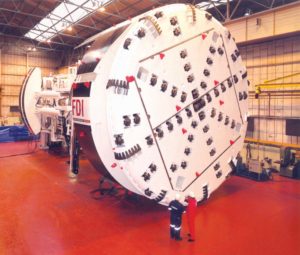
Se equipó a las tres tuneladoras HP con cortadores de 19”, desarrollados por Robbins para el proyecto Svartisen. Además de contar con cortadores más grandes, la construcción de las máquinas se hizo con unos criterios de diseño mucho más robusto que el de las tuneladoras estándar, estando equipadas con rodamientos principales triaxiales, capaces de soportar cargas más elevadas. Las dos TBMs de 4,3 m de diámetro tenían un peso de 262 t, con potencias en cabeza de 2345 kW, permitiendo alcanzar un empuje de 9048 kN en el frente de perforación. Se fabricaron componentes para convertir una de las máquinas a un diámetro de 5 m que, con la instalación de 6 cortadores adicionales, llevaron el peso de la máquina hasta las 290 t. La tercera tuneladora HP, de 180 t de peso, tenía un diámetro de 3,5 m y 1340 kW de potencia en cabeza, capaz de suministrar un empuje al frente de 7800 kN. Su cabeza de corte iba equipada con veinticinco cortadores de 19” de diámetro.
Además de obtener índices de penetración y de avance muy superiores, esta nueva generación de tuneladoras optimizó sus funciones con vistas a su empleo de manera eficaz reduciendo el número de personal para su operación. Los controles remotos y cámaras de televisión instalados en el back-up necesitaban únicamente de un turno de cuatro personas para manejar el sistema: una para pilotar la TBM y llenar los vagones de escombro, un maquinista de locomotora, un electricista y un mecánico para prolongar la vía, cables, ventilación y mangueras.
Perforación del túnel
 Las tres tuneladoras HP alcanzaron resultados impresionantes a lo largo de todo el proyecto. La primera de las dos máquinas de 4,3 m perforó 6021 m de túnel entre septiembre de 1989 y octubre de 1990, con una media de 3,8 m/h en su primer túnel. La máquina convertida a 5 m de diámetro alcanzó una media de 2,74 m/h, con un mejor día de 75,8 m, mejor semana de 312 m y mejor mes de 1068 m de túnel perforado, estableciendo con estos resultados nuevos récords de producción en Noruega.
La segunda máquina de 4,3 m de diámetro perforó 11861 m de túnel entre septiembre de 1989 y abril de 1991, con una media de 3,5 m/h de avance. Esta tuneladora estableció récords mundiales de rendimiento para máquinas entre 4 y 5 m de diámetro con un mejor turno de 61,2 m, mejor día de 90,2 m, mejor semana de 360,5 m y mayor volumen de material excavado en 24 h con 1309 m3.
La tercera máquina comenzó a perforar en Julio de 1990 desde un cruce 4 km adentro del macizo rocoso. Cuando levaba excavados 4700 m de túnel, en mayo de 1991, la tuneladora se encontró con terrenos inestables y afluencias de agua que retrasaron la excavación durante cuatro meses. A pesar de las malas condiciones del terreno, la máquina obtuvo un índice de penetración de 3,7 m/h durante todo el proyecto, perforando una longitud récord de 55,5 m en un solo turno de trabajo.
Ceneri Base Tunnel
Project Overview
 The AlpTransit Project is a massive rail project designed to provide more efficient rail freight routes via base tunnels through the Gotthard and Ceneri mountain ranges. Currently, freight trains traveling up the mountain ranges require pushing locomotives due to steep gradients. The base tunnels will provide a route for freight trains with minimum elevation gain and will shorten passenger train times between Zurich and Milan. Some route times, such as the trip between Lugano and Bellinzona, will be cut in half with the completion of the Ceneri tunnel. The Ceneri Base tunnels and the Gotthard Base tunnels will combine to create a new rail system that will span over 70 km (43 mi) of TBM-driven tunnels and 16 years of construction. The completed rail line is expected to open to traffic in 2019.
In April 2007, Contractor Consorzio Monte Ceneri (CMC) JV – a consortium of CSC, Lugano, Frutiger SA, Thun, Rothpletz, Lienhard + Cie, and Aarau, signed a contract for a 9.7 m (31.8 ft) Robbins machine to bore a 2.4 km (1.5 mi) adit on the Ceneri Base Tunnel Project. The completed adit tunnel joins up at approximately the halfway point of the main rail tunnels. The Main Beam TBM was completely refurbished near Milan, Italy where the cutterhead diameter was changed from 7.6 m (24.9 ft) to 9.7 m (31.8 ft). The TBM was the first machine on the AlpTransit project to utilize 483 mm (19 in) cutters, designed to offer a higher cutter load and longer cutter life resulting in fewer cutter changes. The refurbished machine previously bored successfully on the main headrace tunnel of the Kárahnjúkar Hydropower Project in Iceland.
Geology and Ground Support
Rock in the area consists of schist, Swiss molasse, and Ceneri orthogneiss with a UCS of 30 to 130 MPa (4,300 to 18,800 psi). Much of the tunnel was excavated under high cover of 600 m (2,000 ft). The geology of the tunnel alignment was good for TBM boring, with no squeezing ground or large water inflows encountered. New probe drills, designed in Robbins U.S. locations, were used to verify ground conditions ahead of the TBM. Temporary tunnel support including rock bolts, ring beams and shotcrete were also used depending on geology. Excavated material was temporarily stored at a lot onsite for later preparation as rock aggregate for concrete.
Tunnel Excavation
 On November 6, 2008 excavation of the adit tunnel was completed on schedule after only ten months of boring. Only 30 cutter rings were changed during the last kilometer of boring, with the cutters excavating a combined 160,000 cubic meters (5.9 million cubic feet) of hard rock. Daily advance rates averaged 18.5 m (60.7 ft) – about 61% higher than averages achieved by similar machines boring the Gotthard Base Tunnel using 432 mm (17 in) cutters.
Túnel transandino de Olmos
Descripción del proyecto
 La idea de construir el túnel transandino de Olmos existe desde hace más de 100 años, habiéndose realizado varios intentos para materializarla en la década de 1950 mediante perforación y voladura. El túnel, con una longitud total superior a los 20 km, representa una parte de un proyecto de más envergadura consistente en trasvasar el agua del río Huancabamba, al este de los Andes, a las zonas secas cercanas al océano Pacífico a través de un túnel atravesando la divisoria continental. La primera fase del proyecto incluyó la construcción de una presa de 43 m de altura para desviar el río Huancabamba, cerca de la localidad de San Felipe, a través de las montañas para verter en el normalmente seco río Olmos, al oeste de los Andes. Ahora que el proyecto ya ha entrado en servicio, suministrará más de 2.000 millones de m3 al año de agua para irrigar un área cultivable de 560 km2. Las siguientes fases del proyecto constarán de al menso dos nuevos túneles ejecutados por voladura, dos centrales hidroeléctricas de 600 MW cada una y un sistema de canales para distribuir el agua por la costa.
En Julio de 2004, el Gobierno de Perú y el Gobierno Regional de Lambayeque adjudicaron un contrato de construcción y concesión por 20 años ala General Contratista Concesionaria Trasvase Olmos, S.A. En marzo de 2007, el subcontratista Odebrecht Perú Ingeniería y Construcción, S.A.C (OPIC) comenzó la perforación con la tuneladora abierta Robbins de 5,3 m de diámetro. Dicha máquina se diseñó para perforar un túnel de 12,5 km bajo la cordillera de los Andes, con coberturas de hasta 2000 m de roca dura y potencialmente convergente.
Geología y diseño de la máquina
La tuneladora perforó una geología muy compleja consistente en porfirios de cuarzo, andesita y tobas volcánicas con resistencias a la compresión de 60 a 225 MPa. La traza del túnel atravesaba más de 400 líneas de falla, destacando dos de ellas de anchuras cercanas a los 50 m.
La elevada cobertura del túnel presentó el problema del incremento de temperatura en la galería, llegándose a superar los 54º C. Robbins diseñó unos sistemas de ventilación y refrigeración especiales para hacer que la temperatura disminuyera hasta los 32º C.. Por otra parte, la elevación de la obra, de 1080 m sobre el nivel del mar, hacía que la densidad del aire fuese menor y que la capacidad de disipación de calor del aire se redujera. Los sistemas mencionados hicieron posible introducir una mayor cantidad de aire al túnel para maximizar su refrigeración.
Excavación del túnel
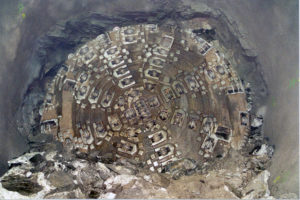
 A finales de 2008 la tuneladora comenzó a perforar en zonas de alta cobertura de roca. Se sufrieron accidentes geológicos de fractura y creación de cavernas, además de registrarse más de 16000 episodios de explosión de roca, imposibles de atenuar con los medios de sostenimiento habituales de cerchas, malla y bulones de roca. Para abordar este problema, Robbins y Odebrecht decidieron modificar los sistemas de sostenimiento instalados por la TBM. Los “dedos” del escudo superior de la máquina se sustituyeron por el sistema de sostenimiento del terreno McNally (ver foto).
El sistema McNally utiliza un conjunto curvo de bolsillos de sección rectangular, que se prolongan axialmente desde la parte posterior de la cabeza de corte hacia el soporte de la cabeza, dentro de la zona de influencia de las perforadoras para sostenimiento. Antes de que se produzca un avance de la TBM, los operarios introducen tiras metálicas o de Madera en los bolsillos, de manera que dichas tiras sobresalgan de los mismos. Estos extremos se fijan a la clave del túnel mediante bulones, operación que se repite con cada avance de la máquina, dejando la pared del túnel cosida contra deformaciones y desprendimientos de roca.
La perforación de las formaciones fracturadas produjo también un desgaste indebido en la cabeza de corte, por lo que los ingenieros de Robbins idearon como protección chapas de acero de 19 mm de espesor y barras de 50 mm, conocidas como “boomerangs” e instaladas como protección de las carcasas de los cortadores ante desprendimientos y explosiones de roca en el frente.
Estas modificaciones a la tuneladora incrementaron de inmediato sus índices de avance, obteniendo rendimientos de hasta 675 m/mes. Este incremento ene le rendimiento fue aún más notable teniendo en cuenta las inundaciones sufridas en abril de 2008 y en marzo de 2009, que borraron las carreteras de acceso a la obra depositando en ella barro hasta 1 m de altura.
Tras cuatro años de perforación en condiciones extremas en una geología tan desafiante, la TBM terminó su camino el 20 de diciembre de 2011. Entre los espectadores del épico cale de la máquina se encontraban personalidades de los gobiernos involucrados, incluyendo al presidente del Perú.
Proyecto East Side Access en Nueva York
Descripción del proyecto
 El proyecto East Side Access en la ciudad de Nueva York consiste en la construcción de una línea subterránea que alivie las congestiones de tráfico entre los distritos de Queens y Manhattan. La línea se prevé que transporte unos 160.000 pasajeros al día entre las estaciones de Grand Central y Sunnyville.
Se conectará Queens con Manhattan por medio de un tubo sumergido de dos pisos bajo el río Este. Dicho tubo sumergido consiste en tramos de hormigón armado instalados en el lecho del río. Su piso superior contiene una línea subterránea operativa mientras que el inferior entrará en servicio a la finalización del proyecto East Side Access, en 2013.
Geología
El proyecto, adjudicado al consorcio Dragados/Judlau, atraviesa terrenos blandos y duros. Los túneles gemelos de 13,7 km entre Grand Central y el lado de Manhattan del túnel sumergido atraviesan esquistos, gneis y granitos con resistencias desde 100 hasta 275 MPa.
Características de los equipos
La tuneladora Robbins excavó los túneles en dirección oeste, consistentes en cuatro tramos cortos que precisaron un diseño especial de la máquina para conseguir trasladarla de ubicación y arrancarla en cuatro puntos diferentes. Los túneles en dirección oeste fueron perforados por otra tuneladora de doble escudo operada por Seli. La tuneladora abierta de alto rendimiento Robbins se diseñó con cabeza de corte atornillada para facilitar su desmontaje, en el que primero se retiraban las piezas perimetrales de la misma mientras que el resto de la parte delantera de la máquina, con un diseño similar al de un paraguas, se retraía hidráulicamente. Este sistema de extensión hidráulica trasladaba radialmente hacia adentro los escudos laterales, inferior y superior de la cabeza, reduciendo su diámetro de 6,7 a 6,1 m después de desmontar dichos escudos.
Para la extracción del escombro, Robbins diseñó un sistema muy complejo de cintas que incluía todos los tipos conocidos de transportadores de este tipo, al objeto de transportar el producto de la excavación a una distancia de 370 m de la obra. El sistema consistió en nueve transportadores distintos que gestionaban el escombro de ambos túneles. Detrás de las tuneladoras se extendieron dos cintas de 914 mm de anchura que descargaban a través de una cinta transversal montada en clave a una cinta fija de 1863 m de longitud instalada en el tubo sumergido.
Desde el túnel se elevó el elevó el escombro mediante una cinta fija vertical con banda de armadura de acero de 23 m de altura, desde donde se transfería al acopio de escombro mediante tres cintas de superficie y un repartidora radial. La segunda de estas cintas de superficie, de 37 m de longitud, atravesaba la autopista Northern Boulevard, una importante arteria de tráfico en Manhattan. Esta cinta se blindó completamente para evitar que los escombros cayesen a la autopista, estando elevada 6 m con respecto a ella. La repartidora radial operaba en la zona de acopio de la estación de Sunnyside. Esta cinta tenía un rango de alcance de 60 grados y creaba pilas de escombro en forma de riñón de 8400 m3 de capacidad.
Excavación del túnel
 La tuneladora Robbins perforó sus cuatro tramos, para un total de 5,2 km excavados bajo la isla de Manhattan. En primer lugar perforó 2,3 km en dirección a Grand Central, transportándose hacia atrás 2 km y dejando instalada vía y sostenimiento. La máquina arrancó de Nuevo en una intersección en forma de Y desde donde perforó tres túneles en cotas distintas.
La perforación del primer túnel comenzó el 30 de septiembre de 2008 y transcurrió durante 907 h netas de funcionamiento. El segundo túnel, de 507 m, terminó el 20 de febrero de 2009 tras 267 h. habiendo terminado su tercer túnel de 1700 m de 2010, la máquina terminó definitivamente sus trabajos con la perforación del cuarto túnel, de 630 m, tras 281 h netas de perforación. El sistema de cintas tuvo una disponibilidad del 90% durante la perforación de los cuatro túneles del proyecto.
Cuando la tuneladora abierta Robbins terminó su proyecto, la tuneladora Seli se estaba preparando para perforar el tercero de sus cuatro túneles en dirección Oeste. Se prevé comenzar los túneles en terreno blando en Queens a finales de 2010. El proyecto completo de la línea East Side Access está programado para su entrada en servicio en 2016.
The Niagara Tunnel Project
Project Overview
 The Niagara Tunnel Project is an ambitious project to tunnel 10.4 km (6.5 mi) from the Sir Adam Beck Generating Complex to above Niagara Falls. The new tunnel will increase the power supply for owner Ontario Power Generation (OPG) by 150 MW and will help to bolster the current power system, which is close to exceeding its capacity during peak months.
OPG awarded the construction contract to Austria-based Strabag AG, who chose a 14.4 m (47.5 ft) diameter Robbins Main Beam TBM to bore the tunnel. The setup included a 105 m (345 ft) long back-up system, which transported 1.7 million m3 (2.2 million cubic yards) of muck over three years via conveyor belt.
Geology
The tunnel is located predominantly in Queenston shale with some limestone, dolostone, sandstone and mudstone up to 200 MPa (29 ksi) UCS. The rock along the tunnel bore path is known to have high in-situ stress and there is potential for squeezing ground. An initial rock support lining of wire mesh, steel ribs, rock bolts, and shotcrete was installed as the TBM advanced. Behind the excavation, an in-situ placed concrete lining is being installed. The final lining will include a waterproofing membrane system to ensure that water does not seep from the tunnel into the rock and cause swelling.
TBM
The Main Beam TBM, the largest hard rock TBM in the world, was assembled at the jobsite using Onsite First Time Assembly (OFTA) in less than 12 months — ahead of a tight delivery schedule. The onsite assembly is considered unprecedented for such a large TBM. The TBM began boring in September 2006.
The Main Beam TBM was also the first ever to utilize back-loading 20-inch cutters, which increase cutter life and reduce cutter changes in hard rock. Both 19-inch and 20-inch cutters could be installed in the cutterhead. The machine had a cutterhead thrust of 18,462 kN (4,150,422 lb) and a maximum torque of 18,670,000 N-m (13,770,285 lb-ft).
Tunnel Excavation and World Records
After about 793 m (2,600 ft) of excavation the TBM entered the Queenston shale formation, where large rock blocks started to fall from the crown before rock support could be placed. In some cases, significant over-break up to 3 m (10 ft) above the cutterhead support was reported.
Strabag ultimately designed a unique ground support system to cope with the geology, which consisted of 9 m (30 ft) long pipe spiles in an umbrella pattern at the crown of the tunnel. Using the new spiling method, over-break was limited to about 0.9 m (3 ft) above the normal tunnel diameter. Nearly 500 m (1,640 ft) of very difficult ground was excavated using this method, at average rates of about 3 m (10 ft) per day.
The new ground support program, done for all excavated ground, consisted of 3 to 4 m (10 to 13 ft) long rock bolts, self-drilling (IBO) anchor bolts, steel straps, wire mesh and wire-reinforced shotcrete. Crews typically bored half a stroke, then began scaling down loose rock and installing rock bolts. After the full 6 ft stroke, the rest of the loose rock was scaled down before installing more rock bolts, wire mesh, steel straps and a layer of shotcrete.
OPG and the contractor also opted to alter the vertical alignment of the tunnel, raising it 46 m (150 ft) to move the tunnel out of the Queenston shale. After 1,981 m (6,500 ft), rock conditions were competent enough that spiling was no longer required.
After surpassing these challenging rock conditions, the machine achieved a world record-breaking month for any TBM 11 m (36 ft) in diameter or larger. During July 2009, the TBM excavated 468 m (1,500 ft) in one month and advanced 153 m (503 ft) in one week overcoming significant geological challenges.
Breakthrough
 May 13, 2011 marked the completion of the TBM’s drive. A well-attended ceremony celebrated the final breakthrough of the 14.4 m (47.2 ft) diameter Robbins Main Beam, following advance into a 300 m (1,000ft) long grout tunnel on March 1, 2011.
While the tunneling portion of the project has reached completion, two years of work still remain. Approximately 30% of the continuous concrete lining was completed during tunneling, with about two thirds of the work still to be done. The finished 12.8 m (42 ft) diameter tunnel will be fully lined with both 600 mm (24 in) thick cast in place concrete and a polyolefin waterproof membrane to prevent leakage. Other construction remaining includes the outlet structure, gates, and removal of the cofferdam in the Niagara River, as well as removal of the rock plug at the outlet end.
Dahuofang Water Tunnel
Project Overview
 The Dahuofang Water Tunnel is a large reservoir diversion project that will transport water from high rainfall areas to the dry, heavily industrialized Shenyang region of China. The total length of the tunnel is 85.3 km (53 mi) with over 60 km (37 mi) being driven by tunnel boring machines (TBM) — one of the world’s longest TBM-driven tunnels.
Geology
The project owners awarded construction contracts in three lots, each about 20 km (12 mi) long. Lot 1, awarded to Beijing Vibroflotation Engineering Co Ltd, chose an 8.03 m (26.3 ft) diameter Robbins Main Beam TBM for the project. The machine is responsible for a 20 km (12 mi) bore in migmatite and orthopyre geology.
The Lot 3 contract was awarded to The Bureau of Water Conservancy and Hydroelectric Power Construction, who chose a nearly identical 8.03 m (26.3 ft) diameter Robbins Main Beam TBM for a 16 km (10 mi) long bore. This section of tunnel also passes through migmatite geology, but about two-thirds of the tunnel contains a complex mixture of heavily weathered and fractured rock.
TBMs
Both Robbins Machines include forty-three 19 in (483 mm) cutters and eight 17 in (432 mm) center cutters. The cutters are backloading with frontloading optional. Both machines use variable frequency drive systems and can generate a maximum thrust of 22,934 kN (5,155,767 lb) and the cutterheads of both machines have a torque of up to 6,275,000 N-m (4,628,202 lb-ft).
Robbins also provided the back-up systems for both machines. Each back-up includes a bridge conveyor, transfer conveyor, track-laying area, and rolling gantries among its units. The TBMs use slightly different conveyor systems — the conveyor for TBM 3 is a shorter length with a consequently reduced power-drive system.
The TBM accessory equipment mounts included probe drills and rock bolting systems, which are compact for working in limited space.
Tunnel Excavation
The Robbins TBMs began boring in June and July of 2005. In March of 2006, after only 8 months of boring, TBMs 1 and 3 had advanced 3.8 and 4.0 km (2.4 and 2.5 mi), respectively. The TBMs completed tunneling in 2007.
The Manapouri Hydroelectric Project
Project Overview
 The Manapouri Hydropower Station is the largest hydropower station in the country and supplies 5100 GWh of electricity annually. In 1997, the project owners, Electricity Corporation of New Zealand (ECNZ), proposed an expansion of the hydropower station from its then output of 585 MW. The plan included a second 9.6 km (6.0 mi) long tailrace tunnel connecting the underground power station at Lake Manapouri to its discharge point in Doubtful Sound.
In 1997 ECNZ awarded the construction contract, worth US $85 million, to a Joint Venture of Fletcher Construction (New Zealand), Dillingham Construction (U.S.), and Ilbau (Austria). The joint venture awarded the contract to Robbins for one 10.05 m (33.0 ft) diameter Main Beam TBM to excavate the tunnel.
Geology
The tunnel passed through Paleozoic metamorphic and igneous rocks. The metamorphic rocks included gneiss, calcsilicate, quartzite, and intrusions of gabbro and diorite. The tunnel geology also included five sub-vertical fault zones with high potential for water inflows.
TBM
Robbins designed the 10.05 m (33.0 ft) diameter TBM for the mixed face hard rock conditions in the tunnel. The Robbins design was then built by Kvaerner-Markham (U.K.) and shipped to the job site. The cutterhead featured sixty-eight 17 inch (432 mm) cutters with loading from either the front or back. Eleven two-speed electric motors powered the cutterhead with 3,463 kW (4,642 hp), generating a torque of 9,859,400 N-m (7,271,919 lb-ft). The 470 m (1,542 ft) long back-up system, built by Rowa Engineering, included a secondary rock-bolting station and a robotic shotcrete station.
Tunnel Excavation
 The Robbins TBM began boring in June 1998 and finished in 33 months. The tunnel progress was divided into four sections, or reaches. During Reach 1, about 1.8 km (1.1 mi) into the bore, the machine experienced few problems. During Reach 2 (spanning 2.4 km (1.5 mi)), the machine encountered heavy water inflows through the fault lines. These inflows reached proportions of 1,300 liters (343 gallons) per second and pressures up to 7.2 MPa (1.0 ksi). These high volumes of inflow necessarily slowed progress throughout Reach 2. Geological conditions improved in Reach 3 (spanning 2 km (1.2 mi)), and by Reach 4 (spanning the final 3.2 km (2.0 mi)) the machine was progressing at a substantial rate.
Despite setbacks due to water, the Robbins TBM suffered no major breakdowns and availability remained high throughout the dig. In addition, total TBM spare parts usage was far below the industry average for this type of job.
Kárahnjúkar Hydropower Project
Project Overview
 The Kárahnjúkar Hydropower Project created the Kárahnjúkar Power Plant to provide 4600 GWh of electricity annually to a nearby aluminum smelting plant. Three dams feed the main Hálslón reservoir and several other dams join the outflow in a combined headrace tunnel to an intake. The intake water travels to the powerhouse through two steel-line vertical shafts and exits from a tailrace tunnel that empties into the Jökulsá i Fljótsdal River.
Project owner Landsvirkjun awarded the construction contract for the hydroelectric project to the Iceland branch of Impregilo S.p.A. The contractor awarded the contract to Robbins for three Robbins Main Beam High Performance TBMs for three lengths of tunnel.
Geology
The machines began boring between April and September 2004 in basalt, moberg, and pillow lava geology up to 300 Mpa (44,000 psi) UCS. A number of fault lines and water inflows were encountered during boring, though the machines made good progress.
TBMs
All three TBMs were the first ever machines designed with back-loading cutterheadsfor 19” cutters. The successful design increased cutter life and reduced the time needed for cutter changes. All of the TBMs were equipped with probe and roof drilling capabilities and were specially designed for the ground conditions. The cutterhead designs featured rock deflectors to protect the cutterhead from fractured and blocky ground, as well as abrasion-resistant wear plates and carbide buttons to bore in abrasive rock.
Tunnel Excavation
Main Headrace Tunnel
By June 2006 the machines had made good progress despite difficult geologic conditions in the tunnels. TBM 1 finished its drive on September 9, 2006 after achieving impressive advance rates with a best month of 864.6 m (2,755 ft) in March 2006. On the same day, TBM 2 tied a world record in its size class after excavating 92 m (302 ft) in 24 hours. The TBM tied the record with another TBM that bored on the Epping to Chatswood Rail Link. TBM 2 finished its initial drive in Fall 2006 and was then disassembled and transported to bore an additional 8.7 km (5.4 mi) long section of the Jökulsá Diversion Tunnel in 2007. The third TBM finished its main tunnel drive on December 5, 2006. All of the TBMs achieved impressive monthly advance rates despite troublesome rock conditions.
Jökulsá Diversion Tunnel
 The Jökulsá Diversion Tunnel adds to the water supply capacity of the powerhouse by connecting the Ufsarlón Reservoir to the main headrace tunnel. Work began in April 2007 and finished in April 2008. During the 8.7 km (5.4 mi) drive, TBM 2 continuously turned in record-breaking performances, beating its own record in June 2007 by excavating 106.1 m (348.2 ft) in 24 hours.
In August 2007, the machine achieved the feat again by excavating 115.7 m (380 ft) in 24 hours and 428.8 m (1,400 ft) in one week. The machine excavated at consistently high rates and finished its bore on schedule.
- Twin Robbins EPBs make milestones near Taj Mahal
- Long Haul TBM: Use of a Rebuilt Main Beam Machine at the DigIndy Tunnel System in Indianapolis, IN
- Evaluating TBM Design and Performance, 30 Years Apart: The Lesotho Highlands Water Tunnel, Phase 1 and Phase 2
- Overcoming Mountainous Geology at Nepal's Sunkoshi Marin Project
- Swift Robbins TBM breaks through 11 Months Early