 Close
Close  Menu
Menu 
Archives: Projects
Black River Tunnel
Onsite Assembly on the Banks of the Black River
Project Overview
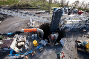
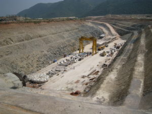
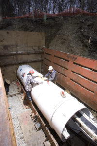
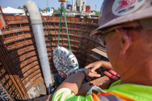 In 2000, the Ohio EPA ordered the City of Lorain to address overflows that violated the City’s National Pollutant Discharge Elimination System (NPDES) permit. After studying options, including the construction of an equalization basin in downtown Lorain, a deep tunnel option was selected. In order to construct the tunnel, the city required the assistance of a USD $65.87 million loan from the Water Pollution Control Loan Fund through Ohio EPA’s Division of Environmental and Financial Assistance. The major components of the Black River Tunnel include the launch shaft and reception shaft – approximately 11 m (36 ft) in diameter and 50 m (165 ft) deep – and the main 1.7 km (1.0 mi) long tunnel with a finished diameter of 5.8 m (19 ft). The project route runs along city property roughly parallel to the Black River, beginning at the launch shaft near the Black River Wharf and terminating near the Black River Wastewater Treatment Plant.
Geology
Ground conditions consisted of soft Cleveland shale, at times layered and laminated in the tunnel crown area.
Onsite First Time Assembly
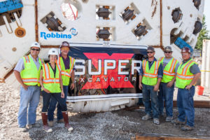
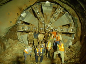
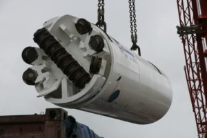
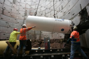
 The mammoth 7.0 m (23 ft) diameter Double Shield machine was built using Onsite First Time Assembly (OFTA)–a Robbins-developed method that saves contractors in shipping time, costs, and man-hours worked. Using the OFTA approach, individual systems are tested prior to delivery but the machine is never fully assembled in the shop. Robbins field service technicians work on location with the contractor to assemble the machine and provide support. Launch of the TBM took place on November 18th, 2013 — approximately three months after assembly began.
Excavation and Breakthrough
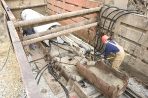
Construction of the main tunnel began in late autumn 2013 with both the Double Shield TBM and continuous conveyor system running at the site. Robbins supplied an in-tunnel continuous conveyor system and space-saving J-type vertical conveyor to provide more open area in the launch shaft.
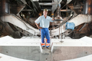
The Double Shield machine was used in a unique manner during boring. The soft shale was excavated with minimal cutter wear, and rather than concrete segments, ring beams were erected within the tail shield for installation as the machine passed. The lagging was spaced at 45 cm (18 inch) intervals with wire mesh panels.
Cleveland shale made for speedy excavation; so fast that it was challenging for the continuous conveyor system to keep up at times. The contractor confirmed that the TBM was mining so fast it could not excavate at its maximum rate. Rehak explained that the fairly soft ground also made for minimal cutter wear, with only seven cutters changed during course of the bore—four of them as a precautionary measure only.
 About 13 sections of bad ground 30 m (100 ft) across were encountered during tunneling, or about 25% of the soft shale geology, which made ground support difficult at times. Those sections consisted of layered and laminated rock that broke from the tunnel crown before ring beams could be expanded, requiring extra chipping and rock relief to expand each rib to the correct diameter. Once workers fine-tuned the technique, they were able to do 12 to 14 rings per day–compared to just one or two rings before the process was refined–even in the sections of bad ground. In more stable sections production averaged 18 to 20 rings per day—a rate the contractor considered very good considering they were erecting steel ribs. Now that tunneling is complete, a final monolithic pour will solidify the lining.
By the time of the machine’s breakthrough on April 29, 2014, the TBM was averaging 21 m (70 ft) per day, and getting up to 24 m (80 ft) per day for multiple days in a row. After tunneling was completed, a final monolithic pour solidified the tunnel lining.
Alimineti Madhava Reddy (AMR)
Project Overview
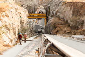
 At 43.5 km (27 mi), the Alimineti Madhava Reddy (AMR) Project will be the longest tunnel without intermediate access in the world when complete. The tunnel will transfer floodwater from the Krishna River to arid regions of India’s Andhra Pradesh state, providing irrigation to 1,200 km2 (400,000 acres) of farmland and clean drinking water to 516 villages.
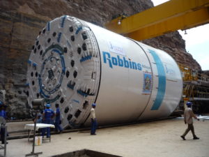
Contractor Jaiprakash Associates Ltd. (JAL) won the USD $413 million engineer-procure-construct contract in 2005 from the Andhra Pradesh government to construct a head regulator and two tunnels, including the main 43.5 km (27 mi) tunnel. On May 26, 2006, JAL awarded a complete contract to The Robbins Company for two 10.0 m (32.8 ft) diameter Double Shield TBMs, as well as conveyor systems, back-up systems, spare parts, personnel, and technical support.
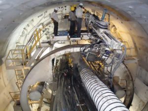
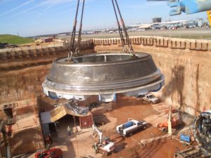
The first of the two machines was launched in March 2008 after an unprecedented onsite assembly. Both of the machines were initially assembled onsite using the Onsite First Time Assembly (OFTA) process. OFTA, rather than assembling the machine in a manufacturing facility, saves both time and money to the contractor in terms of personnel and shipping costs.
Assembly of the first machine took place in a large launch pit at the outlet portal site, using gantry cranes to hoist components into place. Machine parts including the cutterhead, gripper system, forward shield, and telescopic shield were then assembled in a concrete “cradle”. The assembled TBM and back-up then crawled forward by reacting against invert segment pieces installed progressively up to the tunnel entrance. The second Robbins machine was assembled onsite at the opposite end, or the inlet portal.
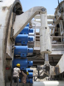
Geologic conditions consist of quartzite zones up to 450 MPa (65,000 psi) UCS, layered and separated by shale for approximately 50% of the length, with granite (160 to 190 MPa/ 23,000 to 28,000 psi UCS) for the remaining 50%. Both machines feature back-loading 20-inch diameter cutters for longer cutter life in the abrasive conditions. Other design modifications include specially designed drive motors to run each machine at a higher than normal rpm for optimal penetration rates in the hard rock.
TBM Launch
AMR Outlet Tunnel
 Initial conditions at the AMR outlet included intermittent power outages, which were supplemented by onsite generators, as well as difficult geology. Severely blocky ground at the outset tore the conveyor belt and slowed the tunneling process. Large rock blocks made their way through the muck buckets, stopping in transfer hoppers and point loading the conveyor system. To counteract this problem, the spacing of grizzly bars on the muck buckets was reduced and additional bars were added so the boulders could not pass onto the conveyor system. Grill bars were also added to the AMR inlet machine in anticipation of similar ground conditions. In good ground, the grill bars can be removed to allow a higher flow of material into the muck hopper.
AMR Inlet Tunnel
 The Inlet machine was one week away from launch in October 2009 when a 100-year monsoon hit the region. The natural coffer dam wall at the inlet site was not designed to withstand a major flood, and was breached by the flood waters. Flood control doors were not opened in time to release the water downstream, causing the significant rise in water levels. The launch pit was inundated with over 20 m (66 ft) of water, leaving the crown of the TBM beneath over 10 m (33 ft) of water for approximately ten days until it could be pumped out.
The TBM and backup were jacked back 12 m from the tunnel face to allow removal of the cutterhead and inspection of the main bearing. Cleanup lasted approximately 14 days which included jet washing the machine and removing silt 300 to 400 mm (12 to 16 in) thick which was left on the machine. A major portion of the TBM components were replaced to get the machine back to running condition.
Tunnel Excavation
The beginning of 2010 (6th km) was marked by the first cutterhead refurbishment, deemed necessary to restore bucket lip housings and face wear plates that were severely worn out after excavation of unusually abrasive and hard rock. After refurbishment, the monthly advance slowly improved to within the range of 300-330m. However, consistently challenging conditions during the same time period in 2010 meant average machine utilization was 21.7%.
 To help avoid sudden breakdowns or delays caused by the constant extremely high vibrations propagating from the cutterhead up to the back-up bridge gantry, a careful inspection of all the exposed components was implemented during and after each stroke, or at any time that a sudden change in boring values or other anomalies occurred. All the cutter fasteners, bucket lip bolts, grill bars, main bearing studs, seal clamp rings, seals and wear bands suffered from the excessive stresses induced and needed to be checked constantly. With the implementation of this regime it was possible to reduce the number of blocked cutters and any possible damage to the head. A second cutterhead refurbishment was planned and carried out in the 12 weeks between June and September 2011 by replacing and removing all damaged carbide wear plates, in particular in the outer/gage section of the head.
When tunneling with limited geological data in a remote location, it is quite often necessary to find technical and practical countermeasures, particularly in the case of AMR where adverse excavation conditions where a large diameter machine is boring one of the world’s longest tunnels. Constant monitoring of the boring data, and a routine maintenance regime play a significant role in the system performance. While hard rock conditions are continuing to be a challenge for both the inlet and the outlet portal tunnels, training of the crew members as to how to deal with the unusually abrasive and hard rock has been invaluable.
As of November 2020, both machines have excavated at least 70% of their respective tunnels. Since the jobsite has continually experienced very hard, abrasive rock conditions, it has allowed for research and testing of harder, more durable cutter rings because of the extreme conditions.
Colector-Interceptor superior del Noroeste
Descripción del proyecto
 El interceptor superior Noroeste (UNWI, Upper Northwestern Interceptor), un proyecto colector de aguas residuales en Sacramento, comprende cerca de 30 km de túneles. El proyecto se creó para asegurar que las necesidades de evacuación de agua presentes y futuras queden cubiertas, especialmente ante las grandes tormentas que acaecen durante la estación húmeda que conllevan el riesgo de desborde de las infraestructuras actuales. El proyecto UNWI se dividió en 9 secciones, comenzando la primera en Natomas y terminando la novena en los barrios de Citrus Heights. En 2008 el proyecto había completado todas sus secciones desde la tercera hasta la novena. El sistema está proyectado para transferir hasta 560 millones de litros de agua residual al día.
El 22 de agosto de 2007, la propiedad Sacramento Regional County Sanitation District (SRCSD) adjudicó el contrato de construcción de las secciones 1 y 2 del proyecto UNWI a la UTE de Traylor y Shea por 97,3 millones de Dólares. Traylor/Shea adquirieron una tuneladora Robbins EPB e 4,25 m de diámetro optimizada para los terrenos a perforar, consistentes en arcillas y arenas sueltas.
Tuneladora EPB
La tuneladora Robbins EPB se diseñó con una cabeza de corte de tipo de radios equipada con chapas de acero antidesgaste. La cabeza de corte disponía de orificios para la inyección de espuma de bentonita al frente de excavación para estabilizarlo y propiciar un flujo suave del escombro. Dicho escombro lo recogía un transportador sinfín de eje de 500 mm de diámetro que descargaba en un sistema de cinta continua Robbins. Se utilizó un sistema de inyección bicomponente para estabilizar aún más el terreno detrás de las dovelas de revestimiento, reduciendo de este modo la posibilidad de asentamientos en superficie. La ventaja de la inyección bicomponente es que la mezcla se podía bombear utilizando equipos de bombeo de hormigón estándar en vez de las bombas de alta presión que normalmente se precisan para la inyección de relleno compuesto por un solo líquido. Reduciendo la presión de bombeo se reducía a su vez la probabilidad de añadir tensiones a los suelos a excavar.
La máquina, dotada de sistemas de articulación active, podía negociar curvas de radio tan reducido como 400 m. Se escogió el diseño de articulación activa para que permitiese el giro de los escudos delantero y trasero independientemente de la acción de los cilindros de empuje, eliminando el problema habitual de deformación de anillos en tramos curvos.
Excavación del túnel
 La EPB comenzó a perforar en enero de 2009 desde la nueva estación de bombeo de Natomas. El terreno a perforar por debajo del eje del túnel consistió en su mayoría en arenas, mientras que la parte superior del frente de excavación estaba compuesta de arcillas. La solera del túnel venía a situarse entre 7 y 14 m bajo la superficie, con presencia de agua a lo largo de toda la perforación.
Para acortar los plazos de construcción, Traylor/Shea y la propiedad SRCSD diseñaron un sistema de revestimiento del túnel nunca utilizado con anterioridad en los EEUU. Las dovelas prefabricadas de hormigón, de 228 mm de espesor se protegieron con láminas de PVC de 1,8 mm. El revestimiento de PVC protege al hormigón del deterioro producido por gases emanados de las aguas residuales, con el resultado final de evitar la instalación de una tubería de transporte y la terminación del túnel inmediatamente operativo con la instalación de las dovelas revestidas, reduciendo el tiempo de puesta en servicio del colector.
Traylor/Shea también decidió utilizar Cintas continuas para la evacuación el escombro dado que en la mayor parte de las ocasiones incrementan la eficacia, su inicio de operación es más sencillo y presentan una mayor disponibilidad que el sistema tradicional de vagones de escombro. El sistema de cinta se diseñó para acomodarlo a las diferentes condiciones de terreno a encontrar en sus 5,7 km de longitud. Entre sus características destacamos los puntos de descarga y tolvas de recepción sellados con uretano y goma para minimizar derrames de material. La espuma y los aditivos bentoníticos ayudaron a mantener una consistencia del escombro que le permitía fluir suavemente hacia las cintas incluso ante la presencia significativa de aguas subterráneas.
La máquina obtuvo en su recorrido algunos de los más altos índices de avance en terreno blando, consiguiendo repetidamente rendimientos de 210 m/semana y 50 m/día, en tres turnos de ocho horas. Además, el sistema de cintas continuas funcionó con una disponibilidad de más del 90% durante toda la obra. La perforación terminó el 21 de noviembre de 2009 cuando la EPB Robbins caló el túnel con dos meses de adelanto sobre la fecha prevista.
West Qinling Rail Tunnels
Twin TBMs set World Records under High Cover
Project Overview
 The West Qinling tunnels are part of the Chinese Government’s Lanzhou to Chongqing Railway, a massive 820 km (500 mi) long scheme that links the capital of Gansu Province (Lanzhou) with southwestern Chongqing, a mega-city of over 35 million people. The parallel rail tunnels are for freight, and link the city of Longnan with the towns of Waina, Luotang and Fengxiang within Gansu Province. The new railway, at a cost of USD $11.3 billion, shortens transport times from 17.5 hours to 6.5 hours and enables an annual freight capacity of 100 million metric tons (110 million US tons). Trains run on the double track lines at 160 km per hour (100 mph), with a 50-train daily maximum.
In January 2009, China Railways signed a contract with Robbins for the supply of twin 10.2 m (33.5 ft) diameter Main Beam machines. The TBMs would be used to excavate two 16.6 km (10.3 mi) tunnels through the Qinling Mountains.
Geology
Geology in the two tunnels consisted of 30 to 80 MPa (4,300 to 11,600 psi) UCS sandstone and phyllite rock beneath more than 1,400 m (4,600 ft) of cover. The corresponding ground support program consisted of continuous mesh and rock bolts, with either ring beams or steel straps, for the length of the tunnel. Rather than roof shield fingers, protected mesh windows were used to install ground support immediately behind the cutterhead. In the event that extremely poor ground was encountered, the mesh pockets could be easily modified to use the McNally Support System, patented by C&M McNally Engineering of Toronto, Ontario, Canada for exclusive use with Robbins TBMs. The McNally System utilizes steel or wood slats to provide continuous support along the roof area of the tunnel, protecting workers from falling rock.
Main Beam TBMs

The two machines, for contractor China Railways 18th Bureau (Group) Co., were assembled at a local workshop and transported to the jobsites, where they were assembled on bridges spanning a deep valley. The first machine, for the Left Line, was launched at the end of June 2010 after being walked through a 2.0 km (1.2 mi) long adit tunnel. The second machine, for the Right Line, was launched on July 17, 2010. The TBM tunnels were just 40 m (130 ft) apart and located approximately 1,000 m (3,280 ft) above sea level, about halfway up Qinling Mountain.
Tunnel Excavation
The two Robbins TBMs advanced at world record rates in exceedingly difficult conditions. The first Main Beam Machine advanced 235 m (771 ft) in one week and 841.8 m (2,761 ft) in one month during Spring 2011 – rates much higher than any ever recorded for TBMs in the 10 to 11 m diameter range. The fast advancing Left Line machine also broke through into an intermediate adit tunnel on May 28, 2011 at the 5.5 km (3.4 mi) mark, where it underwent planned maintenance and inspection. Within several weeks the machine was launched again to bore the rest of its tunnel.
 Despite the conditions of phyllite and limestone with high quartz content, only about 100 cutters were changed on the Left Line TBM. The Right Line machine, launched a month later and about 1,000 m (3,280 ft) behind, also experienced good cutter wear. By 2013, both machines had made their final breakthroughs in their respected tunnels.
Pula Subbaiah Veligonda Project
Double Shield bores Water Transfer Tunnel beneath Indian Tiger Sanctuary
Project Overview
 Beneath India’s largest tiger sanctuary, the Nagarjuna Sagar National Park, tunnel boring machines are orchestrating one of the largest water transfer schemes in India. A Robbins Double Shield TBM is boring tunnel No. 2 of the Pula Subbaiah Veligonda project for Coastal Projects Ltd. (CPL), of the CPL/ Hindustan Construction Company (HCC) JV.
On the Krishna River, on the right bank of the Srisailam Canal, lies the future inlet site for the Pula Subbaiah Veligonda Project. Once complete, the system will draw 1.2 billion cubic meters (317.0 billion gallons) of flood water annually from the foreshore of the Srisailam reservoir. Two parallel, 19.2 km (11.9 mi) long tunnels will transfer water via a network of five canals to over 1,600 square kilometers (395,368 acres) of farmland in the three districts of Prakasam, Nellore, and Kadapa. Up to 243 cubic meters per second (64,193 gallons per second) of water will travel through the bored tunnels to a feeder canal.
In October 2007, a USD $180 Million contract was awarded to Coastal Projects Pvt. Ltd (CPPL). In November, CPPL signed a contract for a 10.0 m (32.8 ft) diameter Robbins Double Shield TBM and continuous conveyor system. In addition to the machine and conveyor, spares and key operating personnel were sent to the jobsite to excavate tunnel No. 2 starting from the outlet end.
The Veligonda tunnel No. 2 is located in sedimentary rock on the western margin of the Cuddapah Basin, where a number of faults and folds make for complex geology. Rock includes quartzite with interbedded shale (60%) and shale with limestone and phyllite (40%) ranging from 90 to 225 MPa (13,000 to 33,000 psi) UCS. Two major faults are present along with some ground water.
Equipment Design
The Double Shield machine utilizes sixty-seven 20-inch diameter back-loading cutters to combat the tough ground conditions. Specially designed drive motors allow the machine to run at a higher than normal RPM, compensating for low penetration rates in the hard rock. In squeezing ground, the cutterhead is also capable of vertical movement allowing for overboring. The machine also has a probe drill which allows for verification of geology 30 m (98 ft) ahead of the TBM. The drill is capable of 360º rotation and can alternatively serve as a grout consolidation drill. Large 40 kW (54 hp) dewatering pumps located on the back-up system have been specially designed to pump any water away from the tunnel face. As the TBM bores, it erects 300 mm (12 inch) thick concrete segments in a 6+1 arrangement, making the final tunnel diameter 9.2 m (30 ft).
Muck haulage requires one of the most extensive conveyor systems ever used in India. The continuous steel cable belt, the longest single flight ever provided by Robbins, will eventually extend 19.2 km (11.9 mi) and requires four main drives and three booster drives.
Launch and Assembly
 The machine was assembled in just four months using Onsite First Time Assembly (OFTA). OFTA is a process that allows machine components to be initially assembled at the jobsite, rather than in a manufacturing facility, typically providing savings in terms of man-hours and shipping costs. Assembly went well despite harsh local temperatures, which can climb to 45˚C (113˚F) daily. In addition, some components could only be installed at night due to thermal expansion in the midday heat.
Excavation
 The Robbins TBM was launched into difficult ground at rates of up to 330 m (1,080 ft) per month, by adopting an extensive program of probe drilling and pre-grouting. Multiple drill holes were bored 30 m (100 ft) ahead prior to every machine push, and grout was then injected at depths of 25 to 30 m (80 to 100 ft). The Robbins TBM then advanced into an unforeseen area of disturbed geology and was inundated with flowing material. The machine became stuck, despite the probe drilling program. It was freed by excavation of a bypass tunnel and continues to excavate in difficult geology.
Updates of this project will be posted as boring continues.
Proyecto de suministro de agua a la ciudad de Kota
Descripción del proyecto
 Tras sucesivos intentos fallidos durante un periodo de ocho años, únicamente restaban tres galerías en roca dura para finalizar una línea de suministro de agua a la ciudad de Kota en Rajasthan, India. Los contratistas a cargo habían intentado perforar las cuarcitas del proyecto utilizando técnicas manuales de minería o perforaciones dirigidas HDD, siendo ambos métodos abandonados debido a su muy bajo rendimiento. La excavación manual del foso de 11 x 4,5 m en planta se extendió durante cuatro meses con rendimientos de únicamente 200 a 300 mm al día. En 2008 se adjudicó al contratista Vichitra Constructions Pvt. Ltd. La construcción de estas galerías tan complicadas de 50 m de longitud.
La conducción, de 13 km de longitud, es parte del programa gubernamental de desarrollo de infraestructuras en Rajashtan (RUIDP en sus siglas inglesas) y se utiliza para incrementar el suministro de agua de la ciudad al mismo tiempo que se lucha contra su contaminación. El sistema, una vez terminado, suministra 24 millones de litros al día a alrededor de 70000 personas.
Después de evaluar varias tecnologías, Vichitra adquirió una SBU-A Robbins de 1,5 m de diámetro equipada con cortadores de 11,5” así como una perforadora de tornillo ABM Robbins 60-1270). Dichas máquinas las suministró by Robbins Tunneling and Trenchless Technology (India) Pvt Ltd, una subsidiaria de The Robbins Company situada en Nueva Delhi y que también aportó al contratista servicio técnico, personal de obra y servicios de reparación de cortadores.
Geología
La mayoría de galerías atravesaban terrenos cuarcíticos con resistencias de 150 a 200 MPa, encontrándose algunas trazas de suelos y lodos.
SBU-A
Las unidades de perforación de pequeño diámetro (SBU-A), que Robbins fabrica en diámetros que van desde las 24” a las 72”, se utilizan principalmente para la excavación de galerías de menso de 150 m de longitud, complementadas por las perforadoras de tornillo (ABM) y la tubería de acero. La SBU-A se suelda a la tubería y la ABM proporciona el empuje y par necesarios para la excavación. La cabeza de corte circular se equipa con cortadores de disco sencillos para la excavación de roca dura, pudiéndose también utilizar combinaciones de dichos cortadores con cortadores de dos filas de botones de carburo o puntas de carburo simples para la perforación de terrenos mixtos. Los cortadores de disco penetran en el frente rocoso creando una zona de rotura desde donde se propagan las fracturas a la roca. El material situado entre dos zonas de rotura se desprende del frente, siendo recogido por cangilones que lo voltean a las aberturas de la cabeza, desde donde se transfiere a un transportador de tornillo sinfín para su evacuación.
Excavación de las galerías
 Se terminaron tres perforaciones en el otoño de 2008 en roca dura y abrasiva. Estas galerías, que pasaban debajo de vías ferroviarias, se excavaron en dos pasadas de 50 m de longitud desde ambos extremos. La primera pasada, en la que se obtuvieron avances de 1,5 m/h, caló en un foso central situado entre las dos vías a atravesar. Se realizó una tercera perforación de 14 m de longitud bajo una carretera ante las dificultades de realizar la excavación de la roca dura en trinchera.
Dulles Airport Train System
Swift Single Shields Excavate Dulles Airport
Project Overview
 With more than 27 million passengers a year, the Dulles International Airport is one of the busiest hubs in the country. The Metropolitan Washington Airports Authority, project owner, created a scheme to maximize transportation efficiency at the airport via an extensive subway system. The new rail line, called the Airport Train System (ATS), was designed to eliminate the previous system of rubber-tired surface vehicles, which added to airport congestion. The USD $1.2 billion project includes a fleet of 29 rail cars capable of traveling up to 68 km/hr (42 mph) between stations.
While excavated using a variety of methods, a 560 m section needed to be TBM-driven due to the location of an active concourse directly overhead. The Atkinson/Clark/Shea JV, contractor for the twin tunnels, awarded a complete contract to Robbins in 2004for two 6.4 m (21.1 ft) diameter TBMs, back-up systems, cutters, and spare parts.
Geology
The tunnel passed through mudstone, sandstone and siltstone geology from 32 to 48 MPa (4,700 to 7,000 psi) UCS. Conditions in the tunnel required immediate grouting at the tail shield to limit settlement.
TBMs
The owner specified Single Shield TBMs due to the short tunnel lengths, tunnel lining requirements, and immediate grouting requirements. Robbins refurbished the Single Shield TBMs, which were originally built in 1985 for the Taipei Metro Subway. Each machine received a new cutterhead, back-up system, thrust controls, and segment erector.
The machines were fitted with 15″ diameter disc cutters to bore in relatively soft rock. The back-up system was designed as an open gantry system for single-track muck cars.
Tunnel Excavation
 Each of the TBMs bored two tunnel drives, 460 m and 100 m (1,500 ft and 335 ft) in length. The TBMs bored the first 460 m (1,500 ft) section and were then walked through the 180 m (600 ft) long Concourse B station, excavated by cut and cover, to their second heading. While the TBMs bored, precast concrete segments were erected within the TBM tail shield to form the tunnel lining. Both TBMs had to maneuver through sharp turns with radii of 125 m (410 ft) as they approached the Main Terminal.
The machines broke through in September 2006. Many other methods including the New Austrian Tunneling (NATM) method and digger shields were used on the project as well. Phase 1 is slated for completion in 2009 and will provide rail service from both Concourse B and Concourse C to the main Terminal.
Milford Haven Gas Connection Project
Motorized SBUs Power through Rock on U.K. Pipeline
Project Overview
 In one of the U.K.’s most extensive infrastructure developments, the Milford Haven Gas Connection Project extends over 300 km (190 mi) across South Wales. The pipeline was created to deliver liquefied natural gas (LNG) from a port at Milford Haven, providing up to 20% of the U.K.’s natural gas for owner National Grid.
Constructed in two phases, work began on the pipeline in early 2006. Both phases were finished in November 2007. Phase I involved a 120 km (75 mi) long stretch from the towns of Milford Haven to Aberdulais. Phase II of the project extended the pipeline another 185 km (115 mi) from Felindre to Tirley in Gloucestershire.
General Contractor NACAP/Land & Marine constructed many of the crossings for both Phases I and II, subcontracting some hard rock crossings to local contractor B&W Tunnelling Ltd. B&W utilized three 1.2 m (48 inch) Robbins SBU-As and two 1.2 m (48 inch) Robbins SBU-Ms to excavate 62 crossings ranging from 20 to 80 m (65 to 260 ft) in length.
Geology
The majority of crossings were located in siltstone and mudstone rock (70 to 200 MPa/ 10,000 to 29,000 psi UCS), with some interbedded clay and gravel.
Motorized SBU
B&W Tunnelling opted for the Motorized SBU (SBU-M) due to the challenging contractual line and grade restrictions on their four longest bores. The 50 mm (2 in) tolerance meant they needed a machine with increased accuracy and continuous monitoring.
The Motorized SBU is a manned-entry, hard rock boring machine used for longer bores (over 150 m/ 500 ft in length) and for line- and grade-critical crossings. The machine is used in conjunction with a standard Auger Boring Machine (ABM) or pipe jacking unit and is welded to the lead casing in the same fashion as SBU-As. The machine is continuously steered from an operator’s console inside the rear shield, and uses a laser targeting system to monitor the machine’s heading.
B&W utilized two Motorized SBUs, one for hard rock and one for mixed ground. The mixed ground cutterhead featured 9.5″ diameter single disc cutters and larger muck openings to tackle the sections of rock interbedded with clay and gravels.
Tunnel Excavation
 All crossings were excavated successfully, typically averaging from 1.5 to 2.0 m (5.0 to 6.5 ft) per hour. Each of the SBU-A crossings utilized a 1.2 m (48 inch) ABM and required shallow launch pits measuring 24 m (80 ft) long x 3 m (10 ft) wide. Incredibly, the three SBU-A machines completed 53 crossings of 30 m (100 ft) in length (a total of approximately 1,600 m/ 5,300 ft bored) with only a single cutter change.
Each of the Motorized SBU crossings required the use of 10 to 30 m (33 to 100 ft) deep launch and recovery shafts. The 10.5 m (35 ft) diameter shafts were lined with concrete-bolted segmental rings and were used to install the pipeline after the crossing had been excavated. Sacrificial casing (steel, 1.2 m/ 48 in O.D.) was used to provide the necessary forward thrust to the cutting face from the ABM. The pipe was later removed and a semi-automatic welding bug was used to install the final pipeline.
Chester Boulevard Interceptor Sewer
Rockhead Makes Short Work of Indiana Crossings
Project Overview
 The city of Richmond, Indiana is a growing community of 50,000 people. To meet future projections, the city created a plan to double the current capacity of its sewer system via a 6.4 km (4 mi) long extension. The new gravity sewer would also eliminate the need for costly pump stations.
In December 2006, the Richmond Sanitary District awarded a USD $4.7 million contract to general contractor Brackney, Inc for construction of the Chester Boulevard Interceptor Sewer—a 3.2 km (2 mi) stretch of the new pipeline to provide service to a commercial district and nearby hospital. Subsequently, Midwest Mole, Inc. was subcontracted by Brackney to excavate four hard rock crossings underneath a river and historic walking trails. Midwest Mole opted to use a 1.2 m (48 inch) diameter SBU-A for the two shortest bores (55m / 180 ft in length), and a 1.4 m (54 inch) Single Shield Rockhead for the two longest bores of 120 m (400 ft) each.
Geology
The crossings were located in shale and limestone rock up to 70 MPa (10,200 psi) UCS. All of the crossings were in competent ground with little to no water inflows.
Rockhead
 Rockheads are the most efficient technology for hard rock or mixed ground conditions from 25 to over 175 MPa (4,000 to over 25,000 psi) UCS that are above the water table. Midwest Mole decided on a Robbins Rockhead for the longest bores due to the length of the crossings and the strict line and grade requirements. Both crossings required accurate excavation at a grade of 0.25%–an easy feat for the Rockhead, which is continuously steered via an operator’s console inside the machine’s rear shield.
The cutterhead on the 1.4 m (54 inch) machine was fitted with 6.5″ diameter patented Single Disc Cutters for optimal boring in solid rock. The machine is owned by Midwest Mole and had been used on six previous projects since 2005. After boring over 1,200 m (3,900 ft), the machine was sent in to the Robbins shop for its first refurbishment and change of cutters prior to the set of gravity sewer crossings.
Tunnel Excavation
Midwest Mole excavated the first 120 m (400 ft) long crossing in March 2007. The Rockhead was welded to the lead 1.4 m (54 in) diameter steel casing and launched from the bore pit using a pipe jacking system. The machine averaged 6 to 8 m (20 to 26 ft) per 10-hour shift, finishing both on time and within grade requirements.The second crossing excavation began in May 2007, with the machine accomplishing even better excavation rates of up to 9 m (30 ft) per shift.
Both SBU-A crossings were finished with similar results. Each of the 55 m (180 ft) crossings, on a 0.42% grade, required continuous monitoring of the machine’s heading. Stabilizer pads, located in each quadrant of the machine, were used to stabilize the machine and allow for steering during the first 6 to 8 m (20 to 26 ft) of the bore. Crews adjusted the machine’s heading by changing the height of the stabilizer pads using a hydraulic cylinder. After the first 6 to 8 m (20 to 26 ft), monitoring alignment required the use of a dutch level. If the alignment had drifted the auger was then pulled and reset on the correct heading. The machine averaged up to 6 m (20 ft) per 10-hour shift on both crossings.
Proyecto hidroeléctrico Svartisen
Descripción del proyecto
 El 99% de la producción de energía en Noruega procede de centales hidroeléctricas, lo que hace que estos grandes proyectos sean un apieza clave de la infraestructura del país. Este uso tan extenso de energía hidroeléctrica comenzó en 1877, cuando se terminó con éxito su primer proyecto de este tipo. En 1990, Noruega contaba con más de 170 instalaciones hidroeléctricas subterráneas, con aproximadamente 3500 km de túneles y galerías situadas por todo el país. La empresa gestora Statkraft proyecta, construye y opera todas las centrales hidroeléctricas propiedad del gobierno, lo que representa un 28% de la producción total noruega de energía hidroeléctrica. El proyecto Svartisen, situado un poco al norte del círculo polar ártico, consiste en 46 pozos conectados a 40 km de túneles de diámetros entre 3,5 y 5 m. Los túneles están diseñados para recoger y transportar el agua de las montañas glaciares de Trollberget hasta el lago de Storglomvatnet, que es el embalse principal del proyecto. Desde allí se transporta el agua mediante una tubería de presión de 7 km hasta la central de Kilvik, en los Holandsfjorden, a nivel del mar. También se construyen dos túneles de aliviadero para recoger otras aguas provenientes de la formación montañosa.
En 1988 Statkraft encargó a Robbins el suministro de cinco máquinas para la perforación de 57 km de túnel en el nuevo proyecto Svartisen, que representaban un 62% de la longitud total de túnel a excavar para el proyecto. Dos de las máquinas se reacondicionaron para el proyecto, con diámetros de 8,5 y 3,5 m y un objetivo de perforación de 7,3 y 15,4 km respectivamente. Las otras tres tuneladoras se fabricaron especialmente para el proyecto con características de Alto Rendimiento (High Performance, HP), capaces de ejercer un empuje de 312 kN en cada uno des sus cortadores de 19” de diámetro. Estas primeras y revolucionarias tuneladoras HP marcaron el camino para la construcción de túneles en roca dura tal y como hoy la conocemos.
Geología
La geología de la zona de obra consistió principalmente de esquistos micosos y de mezclas de mica y gneis (80% del túnel), metaarenisca (o cuarcita pura), granito y gneis granítico (13%) y caliza y mármol (7%). Las capas de calizas variaban en su espesor desde unos pocos centímetros a potencias de más de 100 m. La existencia de cavernas y de aguas subterráneas se hizo evidente desde la investigación superficial del terreno. Las resistencias a la compresión del macizo rocoso del proyecto Svartisen iban desde 100 hasta 300 MPa. Asimismo, la topografía muy irregular del terreno causaba tensiones excéntricas e irregulares en la roca, sujeta a presiones tectónicas y residuales de carácter extremo. Dado que se previó que la perforación iba a tener lugar en rocas estables, no se previó la instalación de revestimiento en el túnel.
Tuneladoras de alto rendimiento (HP TBMs)
Se equipó a las tres tuneladoras HP con cortadores de 19”, desarrollados por Robbins para el proyecto Svartisen. Además de contar con cortadores más grandes, la construcción de las máquinas se hizo con unos criterios de diseño mucho más robusto que el de las tuneladoras estándar, estando equipadas con rodamientos principales triaxiales, capaces de soportar cargas más elevadas. Las dos TBMs de 4,3 m de diámetro tenían un peso de 262 t, con potencias en cabeza de 2345 kW, permitiendo alcanzar un empuje de 9048 kN en el frente de perforación. Se fabricaron componentes para convertir una de las máquinas a un diámetro de 5 m que, con la instalación de 6 cortadores adicionales, llevaron el peso de la máquina hasta las 290 t. La tercera tuneladora HP, de 180 t de peso, tenía un diámetro de 3,5 m y 1340 kW de potencia en cabeza, capaz de suministrar un empuje al frente de 7800 kN. Su cabeza de corte iba equipada con veinticinco cortadores de 19” de diámetro.
Además de obtener índices de penetración y de avance muy superiores, esta nueva generación de tuneladoras optimizó sus funciones con vistas a su empleo de manera eficaz reduciendo el número de personal para su operación. Los controles remotos y cámaras de televisión instalados en el back-up necesitaban únicamente de un turno de cuatro personas para manejar el sistema: una para pilotar la TBM y llenar los vagones de escombro, un maquinista de locomotora, un electricista y un mecánico para prolongar la vía, cables, ventilación y mangueras.
Perforación del túnel
 Las tres tuneladoras HP alcanzaron resultados impresionantes a lo largo de todo el proyecto. La primera de las dos máquinas de 4,3 m perforó 6021 m de túnel entre septiembre de 1989 y octubre de 1990, con una media de 3,8 m/h en su primer túnel. La máquina convertida a 5 m de diámetro alcanzó una media de 2,74 m/h, con un mejor día de 75,8 m, mejor semana de 312 m y mejor mes de 1068 m de túnel perforado, estableciendo con estos resultados nuevos récords de producción en Noruega.
La segunda máquina de 4,3 m de diámetro perforó 11861 m de túnel entre septiembre de 1989 y abril de 1991, con una media de 3,5 m/h de avance. Esta tuneladora estableció récords mundiales de rendimiento para máquinas entre 4 y 5 m de diámetro con un mejor turno de 61,2 m, mejor día de 90,2 m, mejor semana de 360,5 m y mayor volumen de material excavado en 24 h con 1309 m3.
La tercera máquina comenzó a perforar en Julio de 1990 desde un cruce 4 km adentro del macizo rocoso. Cuando levaba excavados 4700 m de túnel, en mayo de 1991, la tuneladora se encontró con terrenos inestables y afluencias de agua que retrasaron la excavación durante cuatro meses. A pesar de las malas condiciones del terreno, la máquina obtuvo un índice de penetración de 3,7 m/h durante todo el proyecto, perforando una longitud récord de 55,5 m en un solo turno de trabajo.