 Close
Close  Menu
Menu 
Project Categories: Main Beam TBM
Mumbai Water Tunnel
A National Record in Urban, Hard Rock Conditions
Project Overview
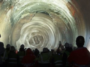
 The Mumbai Water Supply Tunnel runs between the Kapurbawdi and Bhandup areas. The tunnel provides the city’s approximately 20.5 million residents with a reliable water supply, even during the seasonal monsoons that regularly contaminate Mumbai’s water resources. The basalt rock tunnel alleviates Mumbai’s current leakage problems from its aging lines and provide inhabitants with a consistent flow of clean drinking water.
Geology
Abrasive basalt rock and some fractured ground with potential for water inflows.
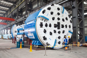
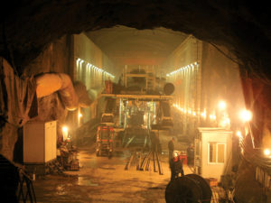
Onsite First Time Assembly
 Onsite First Time Assembly (OFTA) was used to assemble the main bearing, lube system, back-up decks and horizontal, vertical and stacker conveyors. OFTA saved the contractor both time and money by assembling the parts at the jobsite and eliminating pre-assembly at the manufacturing facility in Shanghai, China. The OFTA process took place at the shaft bottom in a 100 m (328 ft) long starter chamber and a 50 m (164 ft) long tail tunnel. TBM components were lowered into the shaft using mobile and gantry cranes.
Excavation and Breakthrough
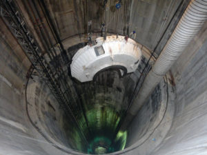
Due to the urban location of the tunnel, the TBM was launched from a 109 m (357 ft) deep shaft, and its launching sequence included an initial start-up excavation of 50 m (164 ft) with vital back-up decks connected to the TBM using cables. The first bore began March 30, 2012 and upon completion, the decks were lowered and a continuous conveyor system was installed for muck haulage and storage.
Robbins provided both the TBM and conveyor system for the project, as well as Field Service personnel to monitor the equipment and assist with daily upkeep and inspection.
 Although the machine was ultimately a success, it did experience its fair share of challenges during the 21-month bore. Difficult ground, including basalt rock, fractured ground, and water inflows, was encountered throughout the tunnel. The tunnel team took all precautionary measures and advanced slowly. The crew maintained good ventilation throughout execution and utilized consistent dewatering to deal with water inflows.
Ground support also played a critical role in poor ground: The rock support system and ring beam erector reduced downtime and stabilized rock. Challenging ground conditions, combined with the sheer depth of the 109 m (357 ft) tunnel, made the machine’s excellent advance rates a particular achievement.
By the end of TBM tunneling, the Robbins machine had reached high rates of 870 m (2,855 ft) per month and 58 m (188 ft) per day, both records for TBM tunneling in India. The contractor stated that the good rates were achieved because of “good performance of the machine and a conveyor system for muck haulage in place of conventional methods.”
West Qinling Rail Tunnels
Twin TBMs set World Records under High Cover
Project Overview
 The West Qinling tunnels are part of the Chinese Government’s Lanzhou to Chongqing Railway, a massive 820 km (500 mi) long scheme that links the capital of Gansu Province (Lanzhou) with southwestern Chongqing, a mega-city of over 35 million people. The parallel rail tunnels are for freight, and link the city of Longnan with the towns of Waina, Luotang and Fengxiang within Gansu Province. The new railway, at a cost of USD $11.3 billion, shortens transport times from 17.5 hours to 6.5 hours and enables an annual freight capacity of 100 million metric tons (110 million US tons). Trains run on the double track lines at 160 km per hour (100 mph), with a 50-train daily maximum.
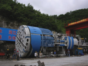
In January 2009, China Railways signed a contract with Robbins for the supply of twin 10.2 m (33.5 ft) diameter Main Beam machines. The TBMs would be used to excavate two 16.6 km (10.3 mi) tunnels through the Qinling Mountains.
Geology
Geology in the two tunnels consisted of 30 to 80 MPa (4,300 to 11,600 psi) UCS sandstone and phyllite rock beneath more than 1,400 m (4,600 ft) of cover. The corresponding ground support program consisted of continuous mesh and rock bolts, with either ring beams or steel straps, for the length of the tunnel. Rather than roof shield fingers, protected mesh windows were used to install ground support immediately behind the cutterhead. In the event that extremely poor ground was encountered, the mesh pockets could be easily modified to use the McNally Support System, patented by C&M McNally Engineering of Toronto, Ontario, Canada for exclusive use with Robbins TBMs. The McNally System utilizes steel or wood slats to provide continuous support along the roof area of the tunnel, protecting workers from falling rock.
Main Beam TBMs

The two machines, for contractor China Railways 18th Bureau (Group) Co., were assembled at a local workshop and transported to the jobsites, where they were assembled on bridges spanning a deep valley. The first machine, for the Left Line, was launched at the end of June 2010 after being walked through a 2.0 km (1.2 mi) long adit tunnel. The second machine, for the Right Line, was launched on July 17, 2010. The TBM tunnels were just 40 m (130 ft) apart and located approximately 1,000 m (3,280 ft) above sea level, about halfway up Qinling Mountain.
Tunnel Excavation
The two Robbins TBMs advanced at world record rates in exceedingly difficult conditions. The first Main Beam Machine advanced 235 m (771 ft) in one week and 841.8 m (2,761 ft) in one month during Spring 2011 – rates much higher than any ever recorded for TBMs in the 10 to 11 m diameter range. The fast advancing Left Line machine also broke through into an intermediate adit tunnel on May 28, 2011 at the 5.5 km (3.4 mi) mark, where it underwent planned maintenance and inspection. Within several weeks the machine was launched again to bore the rest of its tunnel.
 Despite the conditions of phyllite and limestone with high quartz content, only about 100 cutters were changed on the Left Line TBM. The Right Line machine, launched a month later and about 1,000 m (3,280 ft) behind, also experienced good cutter wear. By 2013, both machines had made their final breakthroughs in their respected tunnels.
Гидротехнический проект Свартисен
О проекте
 Примерно 99 процентов всех электрических мощностей в Норвегии генерируют гидроэлектростанции, являющиеся ключевыми в инфраструктуре страны. Впервые в Норвегии начали использовать гидроэнергетику в 1877 году, когда была построена первая гидроэлектростанция. К 1990 году Норвегия имела более 170 подземных гидроэлектростанций, включающих примерно 3500 км тоннелей по всей стране. Заказчик/Подрядчик Statkraft планирует, строит и эксплуатирует все гидроэлектростанции центрального правительства, которые производят 28% годовой выработки электроэнергии в стране. Проект Svartisen, расположенный сразу к северу от Полярного круга, состоит из 46 стволов, соединённых 40 км тоннелей диаметром от 3,5 до 5 м. Тоннели спроектированы для того чтобы принимать и передавать воду с покрытых ледниками гор Trollberget в озеро Storglomvatnet, которое служит водохранилищем. Отсюда вода идёт по 7-километровому подводящему тоннелю к расположенной на уровне моря электростанции в Kilvik, Holandsfjorden. Есть также два открытых канала, по которым добавочное количество воды подаётся из водных источников в предгорьях.
В 1988 году Statkraft заказал у Компании Роббинс пять машин, которыми планировалось пробурить 57 км тоннелей для нового гидротехнического проекта Свартисен, что составляет 62% от общей длины предусмотренных проектом тоннелей. Две из этих машин уже работали ранее на других проектах. Они пробурили соответственно 7,3 км тоннеля диаметром 8,5 м и 15,4 км тоннеля диаметром 3,5 м. В проекте использовались также три новых высокопроизводительных ТБМ (ВП ТБМ) Компании Роббинс, развивавшие усилие подачи на 19-дюймовую шарошку до 312 кН. Эти первые высокопроизводительные ТБМ внесли коренные изменения в мир тоннельных буровых машин. Они проложили путь к технологиям проходки по скальным породам, какие мы знаем сегодня.
Геология
Геологические условия района представлены слюдяными сланцами и слюдяными гнейсами (80 процентов); метапесчаниками (чистыми кварцитами), гранитами и гранитогнейсами (13 процентов), а также известняками и мраморами (7 процентов).
Известняковое основание изменяется по мощности от нескольких сантиметров до 100 м. На поверхность выходят полости и подземные дренажные каналы. Крепость на одноосное сжатие района Свартисен колеблется от 100 МРа и до более 300 МПа. Кроме того, неровная топография вызывала неоднородные напряжения в породном массиве, что ассоциировалось с экстремальными тектоническими и остаточными давлениями. Поскольку устойчивая скальная порода лежала на более 95 процентах общей протяжённости тоннелей, никакая обделка для них не требовалась.
Высокопроизводительные ТБМ
Все три ТБМ были оборудованы 19-дюймовыми шарошками, которые Компания Роббинс разработала специально для проекта Свартисен. Вдобавок к большим диаметрам шарошек, машины имели более мощные, чем у стандартных ТБМ, структурные компоненты, и имели трёхосные главные подшипники для противостояния высоким нагрузкам. Две машины диаметром 4,3 м весили по 262 метрические тонны и передавали мощность 2345 кВт на свои режущие головки, позволяя каждой машине достичь усилия главной подачи на забой в 9048 кН. Для одной из машин поставлялся комплект переоборудования её на диаметр 5 м вместо 4,3 м. При этом добавлялось шесть шарошек при общем весе машины 290 метрических тонн. Третья машина диаметром 3,5 м весила 180 метрических тонн и передавала на режущую головку мощность 1340 кВт, обеспечивая усилие главной подачи в 7800 кН. Режущая головка была оснащена двадцатью пятью 19-дюймовыми дисковыми шарошками.
Вдобавок к высоким скоростям бурения и проходки, новое поколение ТБМ давало возможность эффективно использовать бригаду. Защитовой комплекс каждой системы был оборудован дистанционным управлением и видеокамерами, поэтому требовалось только четыре человека в смену, чтобы работать на машине. Это были оператор ТБМ, он же загружал рельсовые вагонетки; машинист локомотива, электрик и слесарь для наращивания рельсовых путей, кабелей, вентиляции и шлангов.
Проходка тоннеля

Все три высокопроизводительные машины достигли весьма впечатляющих результатов. Первая из двух машин диаметром 4,3 м в период с сентября 1989 года и по октябрь 1990 года прошла на своём первом участке 6021 м тоннеля, в среднем по 3,8 м в час. Будучи модифицирована на диаметр 5 м, она проходила в среднем 2,74 м в час. Лучшая суточная проходка была 75,8 м, лучшая неделя – 312 м и лучший месяц – 1068 м, что является норвежскими рекордами скорости проходки.
Вторая машина диаметром 4,3 м в период с сентября 1989 года и по апрель 1991 года пробурила 11861 м тоннеля, в среднем по 3,5 м в час. На этой проходке машина поставила мировой рекорд в своём классе диаметров от 4 м до 5 м: лучшая смена – 61,2 м, лучшие сутки – 90,2 м, лучшая неделя – 360,5 м и наибольшая выдача породы за сутки: 1309 м3.
Третья машина начала бурение в июле 1990 года, примерно в 4 км от узла пересечения выработок. Пройдя к маю 1991 года около 4700 м тоннеля, машина вошла в слабые породы, сопровождавшиеся большим водопритоком, что замедлило проходку примерно на 4 месяца. Тем не менее, несмотря на сложную геологию, машина всё ещё поддерживала среднюю скорость 3,7 м в час, поставив при этом рекорд проходки за одну смену – 55,5 м.
Ceneri Base Tunnel
Project Overview
 The AlpTransit Project is a massive rail project designed to provide more efficient rail freight routes via base tunnels through the Gotthard and Ceneri mountain ranges. Currently, freight trains traveling up the mountain ranges require pushing locomotives due to steep gradients. The base tunnels will provide a route for freight trains with minimum elevation gain and will shorten passenger train times between Zurich and Milan. Some route times, such as the trip between Lugano and Bellinzona, will be cut in half with the completion of the Ceneri tunnel. The Ceneri Base tunnels and the Gotthard Base tunnels will combine to create a new rail system that will span over 70 km (43 mi) of TBM-driven tunnels and 16 years of construction. The completed rail line is expected to open to traffic in 2019.
In April 2007, Contractor Consorzio Monte Ceneri (CMC) JV – a consortium of CSC, Lugano, Frutiger SA, Thun, Rothpletz, Lienhard + Cie, and Aarau, signed a contract for a 9.7 m (31.8 ft) Robbins machine to bore a 2.4 km (1.5 mi) adit on the Ceneri Base Tunnel Project. The completed adit tunnel joins up at approximately the halfway point of the main rail tunnels. The Main Beam TBM was completely refurbished near Milan, Italy where the cutterhead diameter was changed from 7.6 m (24.9 ft) to 9.7 m (31.8 ft). The TBM was the first machine on the AlpTransit project to utilize 483 mm (19 in) cutters, designed to offer a higher cutter load and longer cutter life resulting in fewer cutter changes. The refurbished machine previously bored successfully on the main headrace tunnel of the Kárahnjúkar Hydropower Project in Iceland.
Geology and Ground Support
Rock in the area consists of schist, Swiss molasse, and Ceneri orthogneiss with a UCS of 30 to 130 MPa (4,300 to 18,800 psi). Much of the tunnel was excavated under high cover of 600 m (2,000 ft). The geology of the tunnel alignment was good for TBM boring, with no squeezing ground or large water inflows encountered. New probe drills, designed in Robbins U.S. locations, were used to verify ground conditions ahead of the TBM. Temporary tunnel support including rock bolts, ring beams and shotcrete were also used depending on geology. Excavated material was temporarily stored at a lot onsite for later preparation as rock aggregate for concrete.
Tunnel Excavation
 On November 6, 2008 excavation of the adit tunnel was completed on schedule after only ten months of boring. Only 30 cutter rings were changed during the last kilometer of boring, with the cutters excavating a combined 160,000 cubic meters (5.9 million cubic feet) of hard rock. Daily advance rates averaged 18.5 m (60.7 ft) – about 61% higher than averages achieved by similar machines boring the Gotthard Base Tunnel using 432 mm (17 in) cutters.
奥莫斯的安第斯山隧道
项目概况

奥莫斯的安第斯山隧道已经有100多年的历史了,在1950年使用钻爆技术进行了几次尝试。这条隧道全长20多公里(12英里),是一项更大工程的一部分,该工程计划将安第斯山脉东侧的Huancabamba河的水输送到太平洋流域的干旱地区,通过一条隧道穿越大陆分水岭。第一阶段包括兴建4300米(140英尺)高的大坝,把位于圣斐利贝村附近的Huancabamba河转移到太平洋一侧的干燥的奥莫斯河上。现在,隧道工程的第一阶段正在运作,该计划每年将提供超过20亿立方米(5000亿加仑)的水用于灌溉560平方公里(13万英亩)的农田。接下来的阶段将包括至少两个钻爆隧道,两个水电站,每一个都发电600兆瓦,一个运河系统来过滤整个海岸的水。
地质条件和机器设计
掘进机面临的是复杂的地质条件:石英云母片岩、安山岩和凝灰岩构成的围岩、UCS(单轴抗压强度)在60至225兆帕(8700至32600 psi)之间。隧道沿线有超过400条断层线,其中两条主要断层线宽约50米(160英尺)
高覆盖层还带来了另外一个问题:隧道内的高温,预计隧道内的温度将超过54摄氏度(130华氏度)。工地高的海拔(1080米/ 3500英尺)导致空气密度较低,每立方米空气的传热能力降低为了应对这种高温环境,罗宾斯公司为这套设备设计了独特的通风和风冷系统:两套相互作用的系统用于把隧道内的温度降到32摄氏度(90华氏度)或更低。
隧道掘进

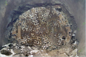
从2008年底开始,掘进机就进入了高埋深隧道段,在那里,工作人员经历了巨大的过度断裂和导管,以及超过16,000个记录的岩石爆裂事件,这些事件无法用铁丝网、岩石螺栓和环梁来控制。为了更好地控制破碎的岩石,罗宾斯和 承包商Odebrecht 通过安装一种新型的掘进机围岩支持来改变。设备的顶部被移走,取而代之的是麦纳利(McNally)围岩支护系统(见右图)。
McNally的工作原理是将弯曲的手指型钢板替换为侧弧形的钢精排储存仓。储存仓轴向从刀盘的背面延伸到刀盘的支撑。在掘进机进入冲程之前,工作人员将金属或木头的板条滑入存储仓,这样,每个储存仓里就有两排的板条。从储存仓伸出的板条的末端,用钢带固定在隧道的顶部。当机器前进时,板条从储存仓中挤压出来,然后用继续把后面的板条用螺栓固定在隧道顶部。为了防止变形和岩石的下落,隧道的长度被板条会继续重新加载使用
穿过断裂和破碎的岩石段的隧道也在刀盘上造成了不必要的磨损。为了解决这个问题,罗宾斯的工程师们增加了19毫米(0.75英寸)厚的磨损板和50毫米(2.0英寸)厚的方形钢,被称为“回力标”,在每一个刀具的前面。回力标从而在遇到状岩石到掌子面岩石爆裂,可以保护刀座。
掘进机的改良让设备的推进速度稳步提高,这台机器每月的进尺达674米(2211英尺)。考虑到2008年4月和2009年3月发生的两起危险的局部洪水,这一改善的速度更加引人注目。这两起洪水淹没了该地区,超过一米的泥浆,并摧毁了道路。
经过四年的奋力开挖和地质条件的挑战,掘进机于2011年12月20日到达了终点。秘鲁包括总统在内的政府官员都一起来到工地见证这一重大的隧道贯通。
East Side Access Project
Project Overview
 New York City’s East Side Access Project involves construction of a new subway line needed to relieve heavy traffic congestion between the boroughs of Queens and Manhattan. The line will serve approximately 160,000 commuters daily between Grand Central and Sunnyside rail stations.
Manhattan and Queens will be connected under the East River via the 63rd Street tunnel, a submersed double-deck tube. The submersed tube consists of reinforced concrete sections barged in place on the riverbed. The tube contains operational subway lines on the top deck, while the bottom deck will become operational when the East Side Access Project is completed in 2013.
Geology
The project, awarded to the Dragados/Judlau JV, is located in a range of geology from soft ground to hard rock. Twin 13.7 km (8.5 mi) long Manhattan Approach Tunnels run from the Manhattan side of the submersed tube up to Grand Central station, with geology consisting of schist, gneiss, and granite from 100 to 275 MPa (14,500 to 40,000 psi) UCS.
Equipment Features
The Robbins TBM excavated the Westbound running tunnels, consisting of four short headings that required a design allowing for swift retraction and re-launching. A second Double Shield TBM, operated by SELI, was used to excavate the Eastbound running tunnels. The Robbins High Performance (HP) Main Beam machine was designed using a segmented, bolt-only cutterhead for easier disassembly. During retraction, the outer components of the cutterhead were removed first. The shielded front section of the TBM, designed as an “umbrella”, was then retracted using hydraulic extensions. The extensions allowed the bottom, side, and roof supports to move radially inwards, reducing the machine diameter from 6.7 m (22.0 ft) when fully extended to just 6.1 m (20.0 ft) with removal of the shield assemblies.
To remove muck, Robbins designed an extensive conveyor system utilizing every commonly recognized type of belt conveyor to transport muck more than 370 m (1,200 ft) away from the jobsite. The system design involved nine separate conveyors handling muck simultaneously from the two tunnels. Two extensible fabric belt conveyors (914 mm/ 36 inches in width) traveled behind the Eastbound and Westbound TBMs, and dumped via a crown-mounted cross conveyor onto a single 1,863 m (6,100 ft) fixed-length conveyor mounted inside the submersed tube.
From the tunnel, muck was transported up the 23 m (75 ft) deep Queens shaft using a fixed-length, steel cable vertical conveyor. Once the muck reached the top of the shaft, it was transferred to the Rail Yard using three overland conveyors and a radial stacker. The second overland conveyor, 37 m (120 ft) in length, crossed Northern Boulevard, a major thoroughfare in Manhattan. This conveyor was designed as a completely enclosed box truss to eliminate debris from reaching the roadway, and sat approximately 6 m (20 ft) above Northern Boulevard and under pre-existing rail lines. Muck was then transferred from the overland conveyors to a radial stacker in the Sunnyside Rail Yard. The radial stacker rotated through 60 degrees to deposit muck in kidney-shaped piles with a capacity of 8,400 cubic meters (11,000 cubic yards).
Tunnel Excavation
 The Robbins machine made four drives, totaling 5.2 km (3.3 mi) beneath Manhattan. The machine first bored 2.3 km (1.5 mi) towards Grand Central Station, and was then retracted 2.0 km (1.2 mi) through the newly bored tunnel, leaving all tracks and tunnel support structures in place. The machine was re-launched at a “Y” shaped intersection to bore three more tunnels at varying elevations.
Boring on the first tunnel commenced on September 30, 2008 with a total of 907 boring hours, and the second, 540 m (1,770 ft) tunnel was finished on February 20, 2009 after 267 boring hours. A third 1.7 km (1.1 mi) long tunnel was completed in February 2010. By June 2010, the machine had completed its fourth and last 630 m (2,060 ft) long drive after 281 boring hours. The conveyor system operated at over 90% availability during the course of the four headings.
At the time of completion for the Robbins Main Beam machine, the SELI TBM was being readied to bore the third of its four Eastbound running tunnels.
Ниагарский тоннель
О проекте

Проект Ниагарского тоннеля – амбициозный проект строительства тоннеля длиной 10, 4 км от Генерирующего Комплекса «Сэр Адам Бек» до реки Ниагара выше по течению от Ниагарского водопада. Со строительством тоннеля генерирующие мощности заказчика – Ontario Power Generation (OPG), – возрастут на 150 МВт и поддержат существующую энергосистему, мощностей которой сейчас едва хватает в пиковые месяцы.
OPG присудила контракт австрийскому подрядчику Strabag AG, Который выбрал для проходки тоннеля ТБМ открытого типа Компании Роббинс. Диаметр машины 14,4 м. С помощью защитового комплекса длиной 105 м и ленточного конвейера за три года было выдано из тоннеля 1,7 миллиона кубических метров породы.
Геология
Трасса тоннеля проходит преимущественно в квинстонских сланцах с включениями участков, представленных известняками, доломитами, песчаниками и алевролитами прочностью на одноосное сжатие до 200 МПа. Известно, что породы, вмещающие тоннель, имеют большое внутреннее напряжение и склонны к пучению. Первичной крепью тоннеля служила стальная сетка, стальные арки, анкера и набрызг-бетон, которые устанавливались по мере продвижения машины. Далее за машиной возводилась монолитная бетонная обделка. Она будет включать гидроизоляционную мембрану, предотвращающую попадание воды из тоннеля в заобделочное пространство и последующее пучение.
ТБМ
ТБМ с главной балкой, или, по-другому, открытая ТБМ, самая большая в мире скальная ТБМ, была смонтирована на стройплощадке без контрольной сборки на заводе. Это заняло меньше 12 месяцев, опережая плотный график поставки. Монтаж такой большой машины без контрольной сборки на заводе и испытаний перед отгрузкой считается беспрецедентным случаем. ТБМ начала бурение в сенгтябре 2006 года.
Эта машина стала также первой, где применялись 20-дюймовые шарошки с задней загрузкой. Такие шарошки имеют увеличенный срок службы, их применение позволяет сократить количество замен шарошек на режущей головке. На режущую головку машины могут устанавливаться как 19-, так и 20-дюймовые шарошки. Машина имеет усилие главной подачи 18462 кН и максимальный момент вращения режущей головки 18670000 Нм.
Проходка тоннеля и мировые рекорды
Пробурив 793 м тоннеля, ТБМ вошла в квинстонские сланцы, где большие блоки породы начали вываливаться из свода тоннеля до установки временной крепи. В некоторых случаях отмечались обрушения кровли тоннеля над режущей головкой на высоту до 3 м.
В конце концов Strabag справился с трудными геологическими условиями, разработав уникальную опережающую крепь из труб длиной 9. Трубы устанавливались в своде тоннеля, образуя своеобразный «зонт». С помощью такой новой технологии удалось уменьшить переборы в кровле тоннеля до примерно 0,9 м. Применяя этот метод, удалось пройти трудный участок длиной примерно 500 м со средней скоростью 3 метра в день.
Согласно новому паспорту временной крепи, устанавливаются анкерная крепь с анкерами длиной от 3 до 4 м, самонарезающиеся анкеры (IBO), стальная затяжка, стальная проволока и набрызг-бетон со стальной фиброй. Обычно бригада проходит половину заходки, затем обирает кровлю и устанавливает анкера. По выполнению полной заходки в 1,8 м, производится окончательная оборка кровли, устанавливается остаток анкерных болтов, стальная сетка, стальная затяжка и наносится набрызг-бетон.
OPG и подрядчик также изменили вертикальный профиль тоннеля, подняв его на 46 м, чтобы уйти из квинстонских сланцев. После 1981 м такой проходки, породный массив стал достаточно устойчивым и от дальнейшего применения опережающей крепи отказались.
Преодолев этот сложный участок, машина достигла мирового рекорда месячной проходки для ТБМ диаметром 11 и более метров. В июле 2009 года ТБМ пробурила 468 метров тоннеля и продвинулась за неделю на 153 метра, преодолев значительные сложности, вызванные неблагоприятной геологией.
Сбойка
 День 13 мая 2011 года стал днём окончания проходки. На хорошо организованной церемонии праздновали финальную сбойку открытой ТБМ Роббинс диаметром 14,4 м. 1 марта 2011 машина начала свой путь, зайдя в 300-метровый портальный участок тоннеля, предварительно пройденный в набрызг-бетонной крепи.
Хотя проходческие работы были завершены, оставалось два года работы над проектом. Приблизительно 30% окончательной обделки было выполнено в течение проходки, а две трети работы ещё оставалось сделать. Тоннель с диаметром в свету 12,8 м будет иметь по всей длине обделку из монолитного бетона толщиной 600 мм, покрытого для предотвращения утечек полиолефиновой мембраной. Остаются работы на выходном портале тоннеля, установка затворов и разборка перемычки на реке Ниагара, а также удаление скальной пробки на выходном портале. Тоннель планируется ввести в работу в 2013 году.
Dahuofang Water Tunnel
Project Overview
 The Dahuofang Water Tunnel is a large reservoir diversion project that will transport water from high rainfall areas to the dry, heavily industrialized Shenyang region of China. The total length of the tunnel is 85.3 km (53 mi) with over 60 km (37 mi) being driven by tunnel boring machines (TBM) — one of the world’s longest TBM-driven tunnels.
Geology
The project owners awarded construction contracts in three lots, each about 20 km (12 mi) long. Lot 1, awarded to Beijing Vibroflotation Engineering Co Ltd, chose an 8.03 m (26.3 ft) diameter Robbins Main Beam TBM for the project. The machine is responsible for a 20 km (12 mi) bore in migmatite and orthopyre geology.
The Lot 3 contract was awarded to The Bureau of Water Conservancy and Hydroelectric Power Construction, who chose a nearly identical 8.03 m (26.3 ft) diameter Robbins Main Beam TBM for a 16 km (10 mi) long bore. This section of tunnel also passes through migmatite geology, but about two-thirds of the tunnel contains a complex mixture of heavily weathered and fractured rock.
TBMs
Both Robbins Machines include forty-three 19 in (483 mm) cutters and eight 17 in (432 mm) center cutters. The cutters are backloading with frontloading optional. Both machines use variable frequency drive systems and can generate a maximum thrust of 22,934 kN (5,155,767 lb) and the cutterheads of both machines have a torque of up to 6,275,000 N-m (4,628,202 lb-ft).
Robbins also provided the back-up systems for both machines. Each back-up includes a bridge conveyor, transfer conveyor, track-laying area, and rolling gantries among its units. The TBMs use slightly different conveyor systems — the conveyor for TBM 3 is a shorter length with a consequently reduced power-drive system.
The TBM accessory equipment mounts included probe drills and rock bolting systems, which are compact for working in limited space.
Tunnel Excavation
The Robbins TBMs began boring in June and July of 2005. In March of 2006, after only 8 months of boring, TBMs 1 and 3 had advanced 3.8 and 4.0 km (2.4 and 2.5 mi), respectively. The TBMs completed tunneling in 2007.
The Manapouri Hydroelectric Project
Project Overview
 The Manapouri Hydropower Station is the largest hydropower station in the country and supplies 5100 GWh of electricity annually. In 1997, the project owners, Electricity Corporation of New Zealand (ECNZ), proposed an expansion of the hydropower station from its then output of 585 MW. The plan included a second 9.6 km (6.0 mi) long tailrace tunnel connecting the underground power station at Lake Manapouri to its discharge point in Doubtful Sound.
In 1997 ECNZ awarded the construction contract, worth US $85 million, to a Joint Venture of Fletcher Construction (New Zealand), Dillingham Construction (U.S.), and Ilbau (Austria). The joint venture awarded the contract to Robbins for one 10.05 m (33.0 ft) diameter Main Beam TBM to excavate the tunnel.
Geology
The tunnel passed through Paleozoic metamorphic and igneous rocks. The metamorphic rocks included gneiss, calcsilicate, quartzite, and intrusions of gabbro and diorite. The tunnel geology also included five sub-vertical fault zones with high potential for water inflows.
TBM
Robbins designed the 10.05 m (33.0 ft) diameter TBM for the mixed face hard rock conditions in the tunnel. The Robbins design was then built by Kvaerner-Markham (U.K.) and shipped to the job site. The cutterhead featured sixty-eight 17 inch (432 mm) cutters with loading from either the front or back. Eleven two-speed electric motors powered the cutterhead with 3,463 kW (4,642 hp), generating a torque of 9,859,400 N-m (7,271,919 lb-ft). The 470 m (1,542 ft) long back-up system, built by Rowa Engineering, included a secondary rock-bolting station and a robotic shotcrete station.
Tunnel Excavation
 The Robbins TBM began boring in June 1998 and finished in 33 months. The tunnel progress was divided into four sections, or reaches. During Reach 1, about 1.8 km (1.1 mi) into the bore, the machine experienced few problems. During Reach 2 (spanning 2.4 km (1.5 mi)), the machine encountered heavy water inflows through the fault lines. These inflows reached proportions of 1,300 liters (343 gallons) per second and pressures up to 7.2 MPa (1.0 ksi). These high volumes of inflow necessarily slowed progress throughout Reach 2. Geological conditions improved in Reach 3 (spanning 2 km (1.2 mi)), and by Reach 4 (spanning the final 3.2 km (2.0 mi)) the machine was progressing at a substantial rate.
Despite setbacks due to water, the Robbins TBM suffered no major breakdowns and availability remained high throughout the dig. In addition, total TBM spare parts usage was far below the industry average for this type of job.
Kárahnjúkar Hydropower Project
Project Overview
 The Kárahnjúkar Hydropower Project created the Kárahnjúkar Power Plant to provide 4600 GWh of electricity annually to a nearby aluminum smelting plant. Three dams feed the main Hálslón reservoir and several other dams join the outflow in a combined headrace tunnel to an intake. The intake water travels to the powerhouse through two steel-line vertical shafts and exits from a tailrace tunnel that empties into the Jökulsá i Fljótsdal River.
Project owner Landsvirkjun awarded the construction contract for the hydroelectric project to the Iceland branch of Impregilo S.p.A. The contractor awarded the contract to Robbins for three Robbins Main Beam High Performance TBMs for three lengths of tunnel.
Geology
The machines began boring between April and September 2004 in basalt, moberg, and pillow lava geology up to 300 Mpa (44,000 psi) UCS. A number of fault lines and water inflows were encountered during boring, though the machines made good progress.
TBMs
All three TBMs were the first ever machines designed with back-loading cutterheadsfor 19” cutters. The successful design increased cutter life and reduced the time needed for cutter changes. All of the TBMs were equipped with probe and roof drilling capabilities and were specially designed for the ground conditions. The cutterhead designs featured rock deflectors to protect the cutterhead from fractured and blocky ground, as well as abrasion-resistant wear plates and carbide buttons to bore in abrasive rock.
Tunnel Excavation
Main Headrace Tunnel
By June 2006 the machines had made good progress despite difficult geologic conditions in the tunnels. TBM 1 finished its drive on September 9, 2006 after achieving impressive advance rates with a best month of 864.6 m (2,755 ft) in March 2006. On the same day, TBM 2 tied a world record in its size class after excavating 92 m (302 ft) in 24 hours. The TBM tied the record with another TBM that bored on the Epping to Chatswood Rail Link. TBM 2 finished its initial drive in Fall 2006 and was then disassembled and transported to bore an additional 8.7 km (5.4 mi) long section of the Jökulsá Diversion Tunnel in 2007. The third TBM finished its main tunnel drive on December 5, 2006. All of the TBMs achieved impressive monthly advance rates despite troublesome rock conditions.
Jökulsá Diversion Tunnel
 The Jökulsá Diversion Tunnel adds to the water supply capacity of the powerhouse by connecting the Ufsarlón Reservoir to the main headrace tunnel. Work began in April 2007 and finished in April 2008. During the 8.7 km (5.4 mi) drive, TBM 2 continuously turned in record-breaking performances, beating its own record in June 2007 by excavating 106.1 m (348.2 ft) in 24 hours.
In August 2007, the machine achieved the feat again by excavating 115.7 m (380 ft) in 24 hours and 428.8 m (1,400 ft) in one week. The machine excavated at consistently high rates and finished its bore on schedule.
- Twin Robbins EPBs make milestones near Taj Mahal
- Long Haul TBM: Use of a Rebuilt Main Beam Machine at the DigIndy Tunnel System in Indianapolis, IN
- Evaluating TBM Design and Performance, 30 Years Apart: The Lesotho Highlands Water Tunnel, Phase 1 and Phase 2
- Overcoming Mountainous Geology at Nepal's Sunkoshi Marin Project
- Swift Robbins TBM breaks through 11 Months Early