 Close
Close  Menu
Menu 
Archives: Projects
Black River Tunnel
Onsite Assembly on the Banks of the Black River
Project Overview
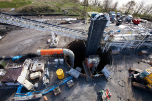
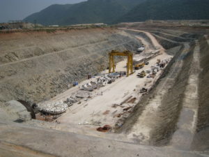
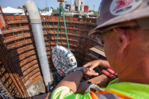 In 2000, the Ohio EPA ordered the City of Lorain to address overflows that violated the City’s National Pollutant Discharge Elimination System (NPDES) permit. After studying options, including the construction of an equalization basin in downtown Lorain, a deep tunnel option was selected. In order to construct the tunnel, the city required the assistance of a USD $65.87 million loan from the Water Pollution Control Loan Fund through Ohio EPA’s Division of Environmental and Financial Assistance. The major components of the Black River Tunnel include the launch shaft and reception shaft – approximately 11 m (36 ft) in diameter and 50 m (165 ft) deep – and the main 1.7 km (1.0 mi) long tunnel with a finished diameter of 5.8 m (19 ft). The project route runs along city property roughly parallel to the Black River, beginning at the launch shaft near the Black River Wharf and terminating near the Black River Wastewater Treatment Plant.
Geology
Ground conditions consisted of soft Cleveland shale, at times layered and laminated in the tunnel crown area.
Onsite First Time Assembly
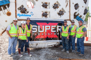
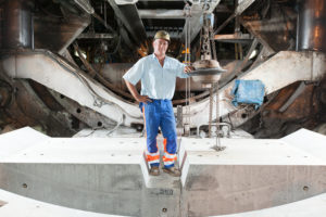
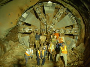
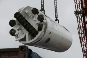
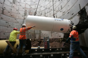
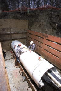
 The mammoth 7.0 m (23 ft) diameter Double Shield machine was built using Onsite First Time Assembly (OFTA)–a Robbins-developed method that saves contractors in shipping time, costs, and man-hours worked. Using the OFTA approach, individual systems are tested prior to delivery but the machine is never fully assembled in the shop. Robbins field service technicians work on location with the contractor to assemble the machine and provide support. Launch of the TBM took place on November 18th, 2013 — approximately three months after assembly began.
Excavation and Breakthrough
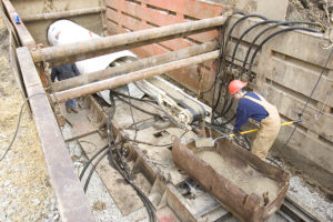
Construction of the main tunnel began in late autumn 2013 with both the Double Shield TBM and continuous conveyor system running at the site. Robbins supplied an in-tunnel continuous conveyor system and space-saving J-type vertical conveyor to provide more open area in the launch shaft.
The Double Shield machine was used in a unique manner during boring. The soft shale was excavated with minimal cutter wear, and rather than concrete segments, ring beams were erected within the tail shield for installation as the machine passed. The lagging was spaced at 45 cm (18 inch) intervals with wire mesh panels.
Cleveland shale made for speedy excavation; so fast that it was challenging for the continuous conveyor system to keep up at times. The contractor confirmed that the TBM was mining so fast it could not excavate at its maximum rate. Rehak explained that the fairly soft ground also made for minimal cutter wear, with only seven cutters changed during course of the bore—four of them as a precautionary measure only.
 About 13 sections of bad ground 30 m (100 ft) across were encountered during tunneling, or about 25% of the soft shale geology, which made ground support difficult at times. Those sections consisted of layered and laminated rock that broke from the tunnel crown before ring beams could be expanded, requiring extra chipping and rock relief to expand each rib to the correct diameter. Once workers fine-tuned the technique, they were able to do 12 to 14 rings per day–compared to just one or two rings before the process was refined–even in the sections of bad ground. In more stable sections production averaged 18 to 20 rings per day—a rate the contractor considered very good considering they were erecting steel ribs. Now that tunneling is complete, a final monolithic pour will solidify the lining.
By the time of the machine’s breakthrough on April 29, 2014, the TBM was averaging 21 m (70 ft) per day, and getting up to 24 m (80 ft) per day for multiple days in a row. After tunneling was completed, a final monolithic pour solidified the tunnel lining.
Alimineti Madhava Reddy (AMR)
Project Overview
 At 43.5 km (27 mi), the Alimineti Madhava Reddy (AMR) Project will be the longest tunnel without intermediate access in the world when complete. The tunnel will transfer floodwater from the Krishna River to arid regions of India’s Andhra Pradesh state, providing irrigation to 1,200 km2 (400,000 acres) of farmland and clean drinking water to 516 villages.
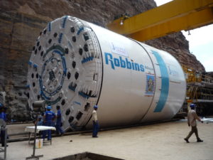
Contractor Jaiprakash Associates Ltd. (JAL) won the USD $413 million engineer-procure-construct contract in 2005 from the Andhra Pradesh government to construct a head regulator and two tunnels, including the main 43.5 km (27 mi) tunnel. On May 26, 2006, JAL awarded a complete contract to The Robbins Company for two 10.0 m (32.8 ft) diameter Double Shield TBMs, as well as conveyor systems, back-up systems, spare parts, personnel, and technical support.
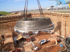
The first of the two machines was launched in March 2008 after an unprecedented onsite assembly. Both of the machines were initially assembled onsite using the Onsite First Time Assembly (OFTA) process. OFTA, rather than assembling the machine in a manufacturing facility, saves both time and money to the contractor in terms of personnel and shipping costs.
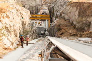
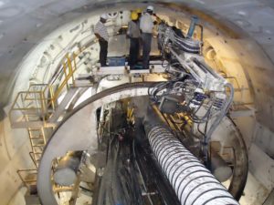
Assembly of the first machine took place in a large launch pit at the outlet portal site, using gantry cranes to hoist components into place. Machine parts including the cutterhead, gripper system, forward shield, and telescopic shield were then assembled in a concrete “cradle”. The assembled TBM and back-up then crawled forward by reacting against invert segment pieces installed progressively up to the tunnel entrance. The second Robbins machine was assembled onsite at the opposite end, or the inlet portal.
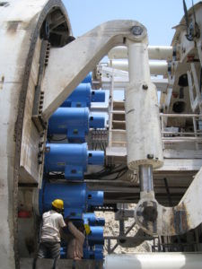
Geologic conditions consist of quartzite zones up to 450 MPa (65,000 psi) UCS, layered and separated by shale for approximately 50% of the length, with granite (160 to 190 MPa/ 23,000 to 28,000 psi UCS) for the remaining 50%. Both machines feature back-loading 20-inch diameter cutters for longer cutter life in the abrasive conditions. Other design modifications include specially designed drive motors to run each machine at a higher than normal rpm for optimal penetration rates in the hard rock.
TBM Launch
AMR Outlet Tunnel
 Initial conditions at the AMR outlet included intermittent power outages, which were supplemented by onsite generators, as well as difficult geology. Severely blocky ground at the outset tore the conveyor belt and slowed the tunneling process. Large rock blocks made their way through the muck buckets, stopping in transfer hoppers and point loading the conveyor system. To counteract this problem, the spacing of grizzly bars on the muck buckets was reduced and additional bars were added so the boulders could not pass onto the conveyor system. Grill bars were also added to the AMR inlet machine in anticipation of similar ground conditions. In good ground, the grill bars can be removed to allow a higher flow of material into the muck hopper.
AMR Inlet Tunnel
 The Inlet machine was one week away from launch in October 2009 when a 100-year monsoon hit the region. The natural coffer dam wall at the inlet site was not designed to withstand a major flood, and was breached by the flood waters. Flood control doors were not opened in time to release the water downstream, causing the significant rise in water levels. The launch pit was inundated with over 20 m (66 ft) of water, leaving the crown of the TBM beneath over 10 m (33 ft) of water for approximately ten days until it could be pumped out.
The TBM and backup were jacked back 12 m from the tunnel face to allow removal of the cutterhead and inspection of the main bearing. Cleanup lasted approximately 14 days which included jet washing the machine and removing silt 300 to 400 mm (12 to 16 in) thick which was left on the machine. A major portion of the TBM components were replaced to get the machine back to running condition.
Tunnel Excavation
The beginning of 2010 (6th km) was marked by the first cutterhead refurbishment, deemed necessary to restore bucket lip housings and face wear plates that were severely worn out after excavation of unusually abrasive and hard rock. After refurbishment, the monthly advance slowly improved to within the range of 300-330m. However, consistently challenging conditions during the same time period in 2010 meant average machine utilization was 21.7%.
 To help avoid sudden breakdowns or delays caused by the constant extremely high vibrations propagating from the cutterhead up to the back-up bridge gantry, a careful inspection of all the exposed components was implemented during and after each stroke, or at any time that a sudden change in boring values or other anomalies occurred. All the cutter fasteners, bucket lip bolts, grill bars, main bearing studs, seal clamp rings, seals and wear bands suffered from the excessive stresses induced and needed to be checked constantly. With the implementation of this regime it was possible to reduce the number of blocked cutters and any possible damage to the head. A second cutterhead refurbishment was planned and carried out in the 12 weeks between June and September 2011 by replacing and removing all damaged carbide wear plates, in particular in the outer/gage section of the head.
When tunneling with limited geological data in a remote location, it is quite often necessary to find technical and practical countermeasures, particularly in the case of AMR where adverse excavation conditions where a large diameter machine is boring one of the world’s longest tunnels. Constant monitoring of the boring data, and a routine maintenance regime play a significant role in the system performance. While hard rock conditions are continuing to be a challenge for both the inlet and the outlet portal tunnels, training of the crew members as to how to deal with the unusually abrasive and hard rock has been invaluable.
As of November 2020, both machines have excavated at least 70% of their respective tunnels. Since the jobsite has continually experienced very hard, abrasive rock conditions, it has allowed for research and testing of harder, more durable cutter rings because of the extreme conditions.
Верхний северо-западный перехватывающий коллектор
О проекте

Верхний северо-западный перехватывающий коллектор канализационной системы Сакраменто, Калифорния, включает около 30 км тоннелей. Система была создана для покрытия текущих и будущих нужд, особенно во время сильных дождей, когда существующие системы рискуют переполниться. Система была разбита на девять участков, причём Участок 1 начинался в Natomas и Участок 9 заканчивался в окрестностях Citrus Heights. Участки с 3 по 9 были построены к 2008 году. Система в состоянии перемещать до 560 миллионов литров стоков в сутки.
22 августа 2007 года заказчик – Региональное Управление Водоснабжения округа Сакраменто (SRCSD), подписал контракт с совместным предприятием Traylor/Shea на завершение строительства Участков 1 и 2 Верхнего северо-западного перехватывающего коллектора. Сумма контракта 97,3 миллиона американских долларов. Подрядчик выбрал для этой работы ТБМ с грунтовым пригрузом Роббинс диаметром 4,25 м, спроектированную специально для работы в глинах и плывунах.
Грунтопригрузная ТБМ
ТБМ с грунтовым пригрузом Роббинс была оборудована режущей головкой спицевого типа с установленными на ней износоустойчивыми плитами. В режущей головке имелись инъекционные порты для нагнетания бентонита и пены, которое стабилизирует забой и обеспечивает плавный поток породы. Порода удалялась шнековым конвейером шахтного типа диаметром 500 мм и поступала на ленту непрерывно удлиняющейся конвейерной системы Роббинс. Для дальнейшей стабилизации грунта и уменьшение риска просадок на дневной поверхности применялось нагнетание заобделочного пространства двухкомпонентным раствором. Преимущество двухкомпонентного раствора в том, что смесь могла закачиваться стандартным бетононасосом, для однокомпонентной бетонной смеси часто требуются насосы высокого давления. Уменьшая давление насоса, было меньше шансов получить подвижки окружающих грунтов.
Машина имела систему активной артикуляции, что позволяло ей проходить кривые радиусом вплоть до 400 м. Активная артикуляция применялась потому, что она позволяет передней и задней оболочкам поворачиваться независимо от цилиндров главной подачи, исключая тем самым общую проблему деформации колец на кривых.
Проходка
 В январе 2009 года машина начала бурение от насосной станции New Natomas. В нижней части забоя встречались, большей частью, пески, тогда как в верхней его части были, в основном, глины. Лоток тоннеля залегал от 7 до 14 м ниже дневной поверхности, грунтовые воды присутствовали повсеместно.
Чтобы ускорить строительство, подрядчик и заказчик захотели применить новый тип тоннельной обделки, до этого в США не использовавшийся. Сборные бетонные сегменты толщиной 228 мм отливались на заводе с покрытием их внутренней поверхности поливинилхлоридными листами толщиной 1,8 мм. Такое покрытие защищало бетон от старения вследствие газовой коррозии. Результатом стал завершённый тоннель, который не требовал установки внутри тоннеля продуктопровода. При этом сократилось время ввода коллектора в эксплуатацию.
Подрядчик, совместное предприятие Traylor/Shea, предпочёл для выдачи породы конвейерную систему с непрерывным удлинением, нежели породные вагонетки, имея в виду длину тоннеля, большую эффективность конвейера, сокращённое время его запуска и, в целом, более высокий коэффициент готовности. Конвейерная система длиной 5,7 км была специально спроектирована для проекта с меняющимися геологическими условиями. Особенностями проекта являются уплотнённые пункты перегрузки породы и приёмные воронки. Чтобы минимизировать просыпи, использована уретановая резина. Добавки в содержащую воду породу, такие как пена и бентонит, создают однородную породную массу, которая будет «течь» на конвейер даже при значительной обводнённости забоя.
В течение проходки машина достигла некоторых самых высоких для машин с грунтовым пригрузом скоростей проходки. Лучшим показателем суточной проходки при трёх восьмичасовых сменах в сутки были 50 м тоннеля. Лучший недельный показатель при пятидневной рабочей неделе – 210 м. Подобные показатели достигались неоднократно. Кроме того, непрерывно удлиняющаяся конвейерная система работала при более чем 90% готовности в течение всего времени бурения. Проходка была закончена 21 ноября 2009 года, опередив график строительства на два месяца.
West Qinling Rail Tunnels
Twin TBMs set World Records under High Cover
Project Overview
 The West Qinling tunnels are part of the Chinese Government’s Lanzhou to Chongqing Railway, a massive 820 km (500 mi) long scheme that links the capital of Gansu Province (Lanzhou) with southwestern Chongqing, a mega-city of over 35 million people. The parallel rail tunnels are for freight, and link the city of Longnan with the towns of Waina, Luotang and Fengxiang within Gansu Province. The new railway, at a cost of USD $11.3 billion, shortens transport times from 17.5 hours to 6.5 hours and enables an annual freight capacity of 100 million metric tons (110 million US tons). Trains run on the double track lines at 160 km per hour (100 mph), with a 50-train daily maximum.
In January 2009, China Railways signed a contract with Robbins for the supply of twin 10.2 m (33.5 ft) diameter Main Beam machines. The TBMs would be used to excavate two 16.6 km (10.3 mi) tunnels through the Qinling Mountains.
Geology
Geology in the two tunnels consisted of 30 to 80 MPa (4,300 to 11,600 psi) UCS sandstone and phyllite rock beneath more than 1,400 m (4,600 ft) of cover. The corresponding ground support program consisted of continuous mesh and rock bolts, with either ring beams or steel straps, for the length of the tunnel. Rather than roof shield fingers, protected mesh windows were used to install ground support immediately behind the cutterhead. In the event that extremely poor ground was encountered, the mesh pockets could be easily modified to use the McNally Support System, patented by C&M McNally Engineering of Toronto, Ontario, Canada for exclusive use with Robbins TBMs. The McNally System utilizes steel or wood slats to provide continuous support along the roof area of the tunnel, protecting workers from falling rock.
Main Beam TBMs

The two machines, for contractor China Railways 18th Bureau (Group) Co., were assembled at a local workshop and transported to the jobsites, where they were assembled on bridges spanning a deep valley. The first machine, for the Left Line, was launched at the end of June 2010 after being walked through a 2.0 km (1.2 mi) long adit tunnel. The second machine, for the Right Line, was launched on July 17, 2010. The TBM tunnels were just 40 m (130 ft) apart and located approximately 1,000 m (3,280 ft) above sea level, about halfway up Qinling Mountain.
Tunnel Excavation
The two Robbins TBMs advanced at world record rates in exceedingly difficult conditions. The first Main Beam Machine advanced 235 m (771 ft) in one week and 841.8 m (2,761 ft) in one month during Spring 2011 – rates much higher than any ever recorded for TBMs in the 10 to 11 m diameter range. The fast advancing Left Line machine also broke through into an intermediate adit tunnel on May 28, 2011 at the 5.5 km (3.4 mi) mark, where it underwent planned maintenance and inspection. Within several weeks the machine was launched again to bore the rest of its tunnel.
 Despite the conditions of phyllite and limestone with high quartz content, only about 100 cutters were changed on the Left Line TBM. The Right Line machine, launched a month later and about 1,000 m (3,280 ft) behind, also experienced good cutter wear. By 2013, both machines had made their final breakthroughs in their respected tunnels.
Pula Subbaiah Veligonda Project
Double Shield bores Water Transfer Tunnel beneath Indian Tiger Sanctuary
Project Overview
 Beneath India’s largest tiger sanctuary, the Nagarjuna Sagar National Park, tunnel boring machines are orchestrating one of the largest water transfer schemes in India. A Robbins Double Shield TBM is boring tunnel No. 2 of the Pula Subbaiah Veligonda project for Coastal Projects Ltd. (CPL), of the CPL/ Hindustan Construction Company (HCC) JV.
On the Krishna River, on the right bank of the Srisailam Canal, lies the future inlet site for the Pula Subbaiah Veligonda Project. Once complete, the system will draw 1.2 billion cubic meters (317.0 billion gallons) of flood water annually from the foreshore of the Srisailam reservoir. Two parallel, 19.2 km (11.9 mi) long tunnels will transfer water via a network of five canals to over 1,600 square kilometers (395,368 acres) of farmland in the three districts of Prakasam, Nellore, and Kadapa. Up to 243 cubic meters per second (64,193 gallons per second) of water will travel through the bored tunnels to a feeder canal.
In October 2007, a USD $180 Million contract was awarded to Coastal Projects Pvt. Ltd (CPPL). In November, CPPL signed a contract for a 10.0 m (32.8 ft) diameter Robbins Double Shield TBM and continuous conveyor system. In addition to the machine and conveyor, spares and key operating personnel were sent to the jobsite to excavate tunnel No. 2 starting from the outlet end.
The Veligonda tunnel No. 2 is located in sedimentary rock on the western margin of the Cuddapah Basin, where a number of faults and folds make for complex geology. Rock includes quartzite with interbedded shale (60%) and shale with limestone and phyllite (40%) ranging from 90 to 225 MPa (13,000 to 33,000 psi) UCS. Two major faults are present along with some ground water.
Equipment Design
The Double Shield machine utilizes sixty-seven 20-inch diameter back-loading cutters to combat the tough ground conditions. Specially designed drive motors allow the machine to run at a higher than normal RPM, compensating for low penetration rates in the hard rock. In squeezing ground, the cutterhead is also capable of vertical movement allowing for overboring. The machine also has a probe drill which allows for verification of geology 30 m (98 ft) ahead of the TBM. The drill is capable of 360º rotation and can alternatively serve as a grout consolidation drill. Large 40 kW (54 hp) dewatering pumps located on the back-up system have been specially designed to pump any water away from the tunnel face. As the TBM bores, it erects 300 mm (12 inch) thick concrete segments in a 6+1 arrangement, making the final tunnel diameter 9.2 m (30 ft).
Muck haulage requires one of the most extensive conveyor systems ever used in India. The continuous steel cable belt, the longest single flight ever provided by Robbins, will eventually extend 19.2 km (11.9 mi) and requires four main drives and three booster drives.
Launch and Assembly
 The machine was assembled in just four months using Onsite First Time Assembly (OFTA). OFTA is a process that allows machine components to be initially assembled at the jobsite, rather than in a manufacturing facility, typically providing savings in terms of man-hours and shipping costs. Assembly went well despite harsh local temperatures, which can climb to 45˚C (113˚F) daily. In addition, some components could only be installed at night due to thermal expansion in the midday heat.
Excavation
 The Robbins TBM was launched into difficult ground at rates of up to 330 m (1,080 ft) per month, by adopting an extensive program of probe drilling and pre-grouting. Multiple drill holes were bored 30 m (100 ft) ahead prior to every machine push, and grout was then injected at depths of 25 to 30 m (80 to 100 ft). The Robbins TBM then advanced into an unforeseen area of disturbed geology and was inundated with flowing material. The machine became stuck, despite the probe drilling program. It was freed by excavation of a bypass tunnel and continues to excavate in difficult geology.
Updates of this project will be posted as boring continues.
Kota City Water Supply Project
Project Overview
 After many failed attempts, spanning the course of eight years, just three hard rock crossings remained on a vital water supply line in Kota City, Rajasthan, India. Previous contractors had attempted to excavate the crossings in hard quartzite using hand mining and HDD, which were later abandoned due to low production rates. Simply hand mining the 11 m (36 ft) long by 4.5 m (15 ft) wide launch pit took four months, at rates of 200 to 300 mm (8 to 12 in) per day. In 2008, Contractor Vichitra Constructions Pvt. Ltd. was contracted to complete the difficult 50 m (164 ft) long crossings.
The 13 km (8 mi) pipeline, part of the government’s Rajasthan Urban Infrastructure Development Plan (RUIDP), was used to increase water supply and fight water contamination problems in the city. The finished system provides 24 million liters (6.3 million gallons) of water per day to about 70,000 people.
After researching various technologies, Vichitra purchased a 1.5 m diameter Robbins Small Boring Unit (SBU-A) with 11.5 inch disc cutters and a Robbins 60-1270 Auger Boring Machine (ABM). The technology was supplied by Robbins Tunneling and Trenchless Technology (India) Pvt Ltd, a local subsidiary based in New Delhi who also provided the contractor with technical support, crew members, and cutter rebuild services.
Geology
Much of the crossings consisted of quartzite rock (200-250 MPa / 29,000-36,000 psi), with some tracts of soil and mud. The excavation was remarkable considering the machine bored rock strengths outside the normal range generally excavated by SBU-As.
SBU-A
Small Boring Units, available in diameters from 24 to 72 inches, are typically used on crossings up to 500 ft in length utilizing a standard Auger Boring Machine (ABM) and steel casing. During excavation, the SBU-A is welded to the lead casing while the ABM provides both torque and forward thrust to the cutting head. The circular cutterhead is fitted with single disc cutters to excavate hard rock, or a combination of single disc cutters, two-row tungsten carbide insert cutters, and carbide bits in mixed ground. Disc cutters penetrate the rock face, creating a “crush zone” through which fractures propagate. Material between adjacent crush zones then falls from the face. Muck scrapers scoop the muck into openings on the cutterhead. Muck is then transferred through a full-face auger for removal.
Crossing Excavation
 Three rail bores were completed by autumn 2008 in abrasive, hard rock. The crossings below a railroad were excavated in two 50-m (164-ft) long passes from either side of the tracks. The first pass, with advance rates of 1.5-m (5-ft) per hour, broke through into a center pit located between the two sets of tracks. A third 14-m (46-ft) long bore was added underneath a roadway after difficulties with open-cut operations in hard rock.
Dulles Airport Train System
Swift Single Shields Excavate Dulles Airport
Project Overview
 With more than 27 million passengers a year, the Dulles International Airport is one of the busiest hubs in the country. The Metropolitan Washington Airports Authority, project owner, created a scheme to maximize transportation efficiency at the airport via an extensive subway system. The new rail line, called the Airport Train System (ATS), was designed to eliminate the previous system of rubber-tired surface vehicles, which added to airport congestion. The USD $1.2 billion project includes a fleet of 29 rail cars capable of traveling up to 68 km/hr (42 mph) between stations.
While excavated using a variety of methods, a 560 m section needed to be TBM-driven due to the location of an active concourse directly overhead. The Atkinson/Clark/Shea JV, contractor for the twin tunnels, awarded a complete contract to Robbins in 2004for two 6.4 m (21.1 ft) diameter TBMs, back-up systems, cutters, and spare parts.
Geology
The tunnel passed through mudstone, sandstone and siltstone geology from 32 to 48 MPa (4,700 to 7,000 psi) UCS. Conditions in the tunnel required immediate grouting at the tail shield to limit settlement.
TBMs
The owner specified Single Shield TBMs due to the short tunnel lengths, tunnel lining requirements, and immediate grouting requirements. Robbins refurbished the Single Shield TBMs, which were originally built in 1985 for the Taipei Metro Subway. Each machine received a new cutterhead, back-up system, thrust controls, and segment erector.
The machines were fitted with 15″ diameter disc cutters to bore in relatively soft rock. The back-up system was designed as an open gantry system for single-track muck cars.
Tunnel Excavation
 Each of the TBMs bored two tunnel drives, 460 m and 100 m (1,500 ft and 335 ft) in length. The TBMs bored the first 460 m (1,500 ft) section and were then walked through the 180 m (600 ft) long Concourse B station, excavated by cut and cover, to their second heading. While the TBMs bored, precast concrete segments were erected within the TBM tail shield to form the tunnel lining. Both TBMs had to maneuver through sharp turns with radii of 125 m (410 ft) as they approached the Main Terminal.
The machines broke through in September 2006. Many other methods including the New Austrian Tunneling (NATM) method and digger shields were used on the project as well. Phase 1 is slated for completion in 2009 and will provide rail service from both Concourse B and Concourse C to the main Terminal.
Milford Haven Gas Connection Project
Motorized SBUs Power through Rock on U.K. Pipeline
Project Overview
 In one of the U.K.’s most extensive infrastructure developments, the Milford Haven Gas Connection Project extends over 300 km (190 mi) across South Wales. The pipeline was created to deliver liquefied natural gas (LNG) from a port at Milford Haven, providing up to 20% of the U.K.’s natural gas for owner National Grid.
Constructed in two phases, work began on the pipeline in early 2006. Both phases were finished in November 2007. Phase I involved a 120 km (75 mi) long stretch from the towns of Milford Haven to Aberdulais. Phase II of the project extended the pipeline another 185 km (115 mi) from Felindre to Tirley in Gloucestershire.
General Contractor NACAP/Land & Marine constructed many of the crossings for both Phases I and II, subcontracting some hard rock crossings to local contractor B&W Tunnelling Ltd. B&W utilized three 1.2 m (48 inch) Robbins SBU-As and two 1.2 m (48 inch) Robbins SBU-Ms to excavate 62 crossings ranging from 20 to 80 m (65 to 260 ft) in length.
Geology
The majority of crossings were located in siltstone and mudstone rock (70 to 200 MPa/ 10,000 to 29,000 psi UCS), with some interbedded clay and gravel.
Motorized SBU
B&W Tunnelling opted for the Motorized SBU (SBU-M) due to the challenging contractual line and grade restrictions on their four longest bores. The 50 mm (2 in) tolerance meant they needed a machine with increased accuracy and continuous monitoring.
The Motorized SBU is a manned-entry, hard rock boring machine used for longer bores (over 150 m/ 500 ft in length) and for line- and grade-critical crossings. The machine is used in conjunction with a standard Auger Boring Machine (ABM) or pipe jacking unit and is welded to the lead casing in the same fashion as SBU-As. The machine is continuously steered from an operator’s console inside the rear shield, and uses a laser targeting system to monitor the machine’s heading.
B&W utilized two Motorized SBUs, one for hard rock and one for mixed ground. The mixed ground cutterhead featured 9.5″ diameter single disc cutters and larger muck openings to tackle the sections of rock interbedded with clay and gravels.
Tunnel Excavation
 All crossings were excavated successfully, typically averaging from 1.5 to 2.0 m (5.0 to 6.5 ft) per hour. Each of the SBU-A crossings utilized a 1.2 m (48 inch) ABM and required shallow launch pits measuring 24 m (80 ft) long x 3 m (10 ft) wide. Incredibly, the three SBU-A machines completed 53 crossings of 30 m (100 ft) in length (a total of approximately 1,600 m/ 5,300 ft bored) with only a single cutter change.
Each of the Motorized SBU crossings required the use of 10 to 30 m (33 to 100 ft) deep launch and recovery shafts. The 10.5 m (35 ft) diameter shafts were lined with concrete-bolted segmental rings and were used to install the pipeline after the crossing had been excavated. Sacrificial casing (steel, 1.2 m/ 48 in O.D.) was used to provide the necessary forward thrust to the cutting face from the ABM. The pipe was later removed and a semi-automatic welding bug was used to install the final pipeline.
Chester Boulevard Interceptor Sewer
Rockhead Makes Short Work of Indiana Crossings
Project Overview
 The city of Richmond, Indiana is a growing community of 50,000 people. To meet future projections, the city created a plan to double the current capacity of its sewer system via a 6.4 km (4 mi) long extension. The new gravity sewer would also eliminate the need for costly pump stations.
In December 2006, the Richmond Sanitary District awarded a USD $4.7 million contract to general contractor Brackney, Inc for construction of the Chester Boulevard Interceptor Sewer—a 3.2 km (2 mi) stretch of the new pipeline to provide service to a commercial district and nearby hospital. Subsequently, Midwest Mole, Inc. was subcontracted by Brackney to excavate four hard rock crossings underneath a river and historic walking trails. Midwest Mole opted to use a 1.2 m (48 inch) diameter SBU-A for the two shortest bores (55m / 180 ft in length), and a 1.4 m (54 inch) Single Shield Rockhead for the two longest bores of 120 m (400 ft) each.
Geology
The crossings were located in shale and limestone rock up to 70 MPa (10,200 psi) UCS. All of the crossings were in competent ground with little to no water inflows.
Rockhead
 Rockheads are the most efficient technology for hard rock or mixed ground conditions from 25 to over 175 MPa (4,000 to over 25,000 psi) UCS that are above the water table. Midwest Mole decided on a Robbins Rockhead for the longest bores due to the length of the crossings and the strict line and grade requirements. Both crossings required accurate excavation at a grade of 0.25%–an easy feat for the Rockhead, which is continuously steered via an operator’s console inside the machine’s rear shield.
The cutterhead on the 1.4 m (54 inch) machine was fitted with 6.5″ diameter patented Single Disc Cutters for optimal boring in solid rock. The machine is owned by Midwest Mole and had been used on six previous projects since 2005. After boring over 1,200 m (3,900 ft), the machine was sent in to the Robbins shop for its first refurbishment and change of cutters prior to the set of gravity sewer crossings.
Tunnel Excavation
Midwest Mole excavated the first 120 m (400 ft) long crossing in March 2007. The Rockhead was welded to the lead 1.4 m (54 in) diameter steel casing and launched from the bore pit using a pipe jacking system. The machine averaged 6 to 8 m (20 to 26 ft) per 10-hour shift, finishing both on time and within grade requirements.The second crossing excavation began in May 2007, with the machine accomplishing even better excavation rates of up to 9 m (30 ft) per shift.
Both SBU-A crossings were finished with similar results. Each of the 55 m (180 ft) crossings, on a 0.42% grade, required continuous monitoring of the machine’s heading. Stabilizer pads, located in each quadrant of the machine, were used to stabilize the machine and allow for steering during the first 6 to 8 m (20 to 26 ft) of the bore. Crews adjusted the machine’s heading by changing the height of the stabilizer pads using a hydraulic cylinder. After the first 6 to 8 m (20 to 26 ft), monitoring alignment required the use of a dutch level. If the alignment had drifted the auger was then pulled and reset on the correct heading. The machine averaged up to 6 m (20 ft) per 10-hour shift on both crossings.
Гидротехнический проект Свартисен
О проекте
 Примерно 99 процентов всех электрических мощностей в Норвегии генерируют гидроэлектростанции, являющиеся ключевыми в инфраструктуре страны. Впервые в Норвегии начали использовать гидроэнергетику в 1877 году, когда была построена первая гидроэлектростанция. К 1990 году Норвегия имела более 170 подземных гидроэлектростанций, включающих примерно 3500 км тоннелей по всей стране. Заказчик/Подрядчик Statkraft планирует, строит и эксплуатирует все гидроэлектростанции центрального правительства, которые производят 28% годовой выработки электроэнергии в стране. Проект Svartisen, расположенный сразу к северу от Полярного круга, состоит из 46 стволов, соединённых 40 км тоннелей диаметром от 3,5 до 5 м. Тоннели спроектированы для того чтобы принимать и передавать воду с покрытых ледниками гор Trollberget в озеро Storglomvatnet, которое служит водохранилищем. Отсюда вода идёт по 7-километровому подводящему тоннелю к расположенной на уровне моря электростанции в Kilvik, Holandsfjorden. Есть также два открытых канала, по которым добавочное количество воды подаётся из водных источников в предгорьях.
В 1988 году Statkraft заказал у Компании Роббинс пять машин, которыми планировалось пробурить 57 км тоннелей для нового гидротехнического проекта Свартисен, что составляет 62% от общей длины предусмотренных проектом тоннелей. Две из этих машин уже работали ранее на других проектах. Они пробурили соответственно 7,3 км тоннеля диаметром 8,5 м и 15,4 км тоннеля диаметром 3,5 м. В проекте использовались также три новых высокопроизводительных ТБМ (ВП ТБМ) Компании Роббинс, развивавшие усилие подачи на 19-дюймовую шарошку до 312 кН. Эти первые высокопроизводительные ТБМ внесли коренные изменения в мир тоннельных буровых машин. Они проложили путь к технологиям проходки по скальным породам, какие мы знаем сегодня.
Геология
Геологические условия района представлены слюдяными сланцами и слюдяными гнейсами (80 процентов); метапесчаниками (чистыми кварцитами), гранитами и гранитогнейсами (13 процентов), а также известняками и мраморами (7 процентов).
Известняковое основание изменяется по мощности от нескольких сантиметров до 100 м. На поверхность выходят полости и подземные дренажные каналы. Крепость на одноосное сжатие района Свартисен колеблется от 100 МРа и до более 300 МПа. Кроме того, неровная топография вызывала неоднородные напряжения в породном массиве, что ассоциировалось с экстремальными тектоническими и остаточными давлениями. Поскольку устойчивая скальная порода лежала на более 95 процентах общей протяжённости тоннелей, никакая обделка для них не требовалась.
Высокопроизводительные ТБМ
Все три ТБМ были оборудованы 19-дюймовыми шарошками, которые Компания Роббинс разработала специально для проекта Свартисен. Вдобавок к большим диаметрам шарошек, машины имели более мощные, чем у стандартных ТБМ, структурные компоненты, и имели трёхосные главные подшипники для противостояния высоким нагрузкам. Две машины диаметром 4,3 м весили по 262 метрические тонны и передавали мощность 2345 кВт на свои режущие головки, позволяя каждой машине достичь усилия главной подачи на забой в 9048 кН. Для одной из машин поставлялся комплект переоборудования её на диаметр 5 м вместо 4,3 м. При этом добавлялось шесть шарошек при общем весе машины 290 метрических тонн. Третья машина диаметром 3,5 м весила 180 метрических тонн и передавала на режущую головку мощность 1340 кВт, обеспечивая усилие главной подачи в 7800 кН. Режущая головка была оснащена двадцатью пятью 19-дюймовыми дисковыми шарошками.
Вдобавок к высоким скоростям бурения и проходки, новое поколение ТБМ давало возможность эффективно использовать бригаду. Защитовой комплекс каждой системы был оборудован дистанционным управлением и видеокамерами, поэтому требовалось только четыре человека в смену, чтобы работать на машине. Это были оператор ТБМ, он же загружал рельсовые вагонетки; машинист локомотива, электрик и слесарь для наращивания рельсовых путей, кабелей, вентиляции и шлангов.
Проходка тоннеля

Все три высокопроизводительные машины достигли весьма впечатляющих результатов. Первая из двух машин диаметром 4,3 м в период с сентября 1989 года и по октябрь 1990 года прошла на своём первом участке 6021 м тоннеля, в среднем по 3,8 м в час. Будучи модифицирована на диаметр 5 м, она проходила в среднем 2,74 м в час. Лучшая суточная проходка была 75,8 м, лучшая неделя – 312 м и лучший месяц – 1068 м, что является норвежскими рекордами скорости проходки.
Вторая машина диаметром 4,3 м в период с сентября 1989 года и по апрель 1991 года пробурила 11861 м тоннеля, в среднем по 3,5 м в час. На этой проходке машина поставила мировой рекорд в своём классе диаметров от 4 м до 5 м: лучшая смена – 61,2 м, лучшие сутки – 90,2 м, лучшая неделя – 360,5 м и наибольшая выдача породы за сутки: 1309 м3.
Третья машина начала бурение в июле 1990 года, примерно в 4 км от узла пересечения выработок. Пройдя к маю 1991 года около 4700 м тоннеля, машина вошла в слабые породы, сопровождавшиеся большим водопритоком, что замедлило проходку примерно на 4 месяца. Тем не менее, несмотря на сложную геологию, машина всё ещё поддерживала среднюю скорость 3,7 м в час, поставив при этом рекорд проходки за одну смену – 55,5 м.
- Cooperative Innovation at the Manhattan Tunnel Project: Digger Shields with Expandable Segments to Excavate Complex Fill
- Robbins celebrates TBM acceptance for Ellicott City North Tunnel
- Huge Robbins Slurry TBM breaks through in Hiroshima
- Robbins TBMs break through at Delhi Metro DC-07 Project
- RETC 2025