 Close
Close  Menu
Menu 
Year: 2016
The Next Generation of TBMs for Mining Applications
TBMs have been used in mining in decades past, but their use has been limited and sporadic, due to both perceived and actual application difficulties. With new technology and mounting success stories, this is changing. For both coal and metallurgical mining, deep ore bodies require long access tunnels, and an efficient and economical method of reaching those deposits.
Today, mining engineers are considering TBMs as part of the overall mine development plan. Planned TBM mine drifts are not only longer, but have more complicated trajectories. Mine development TBMs will have to cope with varying geology, potential for high water inflows, steep gradients, and high temperatures. TBM systems are being planned to cope with such difficulties. TBM systems will be considered and increasingly deployed for mine development, even if commodity prices remain low. TBMs can satisfy the need for increased productivity, better life of mine infrastructure, and safety.
This paper will review the historical use of TBMs in mining, and will discuss the 2015 status of TBMs in mining, and the special requirements and adaptable features needed in order to make efficient TBMs a reality in mines worldwide.
Concurrent Segment Lining and TBM Design: A Coordinated Approach for Tunneling Success
The success of a tunnel project relies on many factors, but one of the most important is also the most overlooked: coordination by all parties involved during the design stages. This is particularly true of segment design and TBM design. Tunnel lining with segmental rings is usually designed according to the standards of reinforced concrete construction based on a given GBR. However, for TBM tunneling, the determination of loads during ring erection, advance of the TBM, earth pressure, and bedding of the articulated ring are all part of the tunnel lining design as well. TBM design can be heavily affected by the segment arrangement, dimension, and weight, but these are usually given as a fixed input to the TBM manufacturer—a process that can cause unnecessary complications.
The authors propose that the industry evaluate the process as it stands. In order to find the optimum balance between lining design and TBM cost and operational workflow, both designs should be finalized concurrently. This requires coordination between the TBM manufacturer and segment designer from the early stages. The aim of this paper is to evaluate the influence of the segment lining design on TBM cost and performance, and to provide commentary on existing design guidelines to optimize lining and TBM procurement.
The Brenner Base Tunnel: A European Core Project
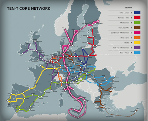
Figure 1. The Trans-European Network for Transport (TEN-T) aims to connect all European member nations from West to East and and North to South.
Tunneling is a worldwide business with often-changing markets. At the moment, everybody is watching the markets in Asia and in particular various huge projects in China and India, as well as the Middle East. With these busy hot spots, it’s easy to overlook projects elsewhere.
In this blog, I want to refocus and take a look at Europe, where there are some very interesting and challenging mega-projects underway for the Trans-European Network for Transport (TEN-T) of the European Union. The TEN-T connects all economies in the European Member Countries from West to East and North to South (Figure 1). This master plan for connectivity in Europe includes nine core network corridors with several projects crossing the borders of multiple European countries. The cross-border project implementation is complicated because of the different technical, financial and statutory requirements.
TEN-T core network projects
The core projects of the TEN-T master plan all serve as missing links that would connect the European Member Countries, like the Koralm and Semmering Railway Tunnels (both in Austria), Lyon-Turin Railway Project (connecting France and Italy), Fehmarn Belt Crossing (connecting Denmark and Germany), Brenner Base Tunnel (connecting Austria and Italy), Ceneri Base Tunnel (connecting Switzerland and Italy) and also some completed projects like the Oresund Bridge, Tunnel Road and Rail Fixed Link (connecting Sweden and Denmark), Milano-Roma-Napoli Railway (Italy), Gotthard and Lötschberg Base Tunnels (Switzerland), Betuwelijn Railroad (connecting the Netherlands and Germany) and the Channel Tunnel (connecting United Kingdom and France).
Financial support from the European Union in an amount estimated at 500 billion euro is required to complete this Trans-European Network and to widen some of the bottlenecks within it. The Brenner Base Tunnel is one of the most interesting cross-border projects and a core project of the TEN-T master plan (Figure 2).
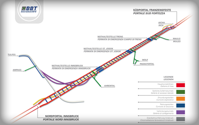
Figure 2. Layout of the Brenner Base Tunnel construction.
Brenner Tunnel Conversations
The Brenner Base Tunnel (BBT) is a big challenge for all involved parties. In 2015, I had the great opportunity to interview Prof. Konrad Bergmeister, who has been the CEO of the BBT SE since August 2006 (Figure 3). Bergmeister was previously the technical director and head engineer of the company managing the Brenner Highway and was responsible for the planning and construction of new infrastructure and for maintenance of the existing structures. For the past 22 years, he has taught construction engineering at the University of Natural Resources and Applied Life Sciences in Vienna (Austria). He has been the President of the Free University in Bolzano (Italy) since 2010.
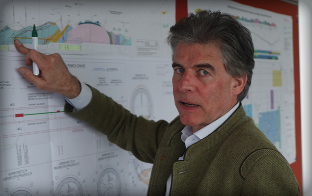
Figure 3. Professor Konrad Bergmeister, the CEO of BBT SE since 2006.
Interview with Prof. Bergmeister
Could you give me a brief overview of the Brenner Base Tunnel?
The Brenner Base Tunnel is a ground-breaking engineering project for the 21st century. This underground structure has a total length of 64 km and consists of three tubes: the exploratory tunnel and two main tubes with four lateral access tunnels connecting them together (Figure 4). The tunnel itself will become the longest railway tunnel in the world once complete.
The history of the tunnel is a long one: 160 years ago, an Italian engineer came up with the idea to go beneath the Brenner Pass. After World War Two, the project was reassessed but never proceeded. Finally, between 1987 and 1989 a feasibility study was carried out. The preliminary project was approved in 2002, and between 2005 and 2008 project details were worked out. In 2009 the environmental and technical approvals were obtained in Austria and in Italy. So we started with the first exploration of the whole rock situation in 2006, drilling vertical bore holes that totalled more than 28 km when we sum it all up. And this preliminary information was used in order to study the final layout of the tunnel in order to do the definitive design.
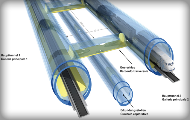
Figure 4. The 64 km long Brenner Base Tunnel consists of three tubes: An exploratory bore and two main tubes connected by access tunnels.
What, for an engineer, is the most challenging aspect of the Brenner Base Tunnel?
The most challenging issues for me are the following:
First of all we developed the so-called design guide in order to have the right basis to execute the design in both countries. This design guide was based on some new design ideas taking into account all the safety issues that have been proposed with the Eurocodes on a European level.
Second we developed internally a so-called chance and risk analysis, which should allow us to monitor the development of the project in terms of possible chances and risks. How we are doing that? Well we are trying to evaluate and double check the actual ongoing construction with our project managers and external experts and we are trying to identify all the possible risks and chances that might occur as tunneling proceeds. This analysis is part of a database that will be actualized on a yearly basis so we have additional information in terms of possible risks, additional costs, cost savings and scheduling.
The third issue is something that deals with some novel forecast technologies. We are using digital mapping and photogrammetric mapping as forecasting methods, particularly for the ongoing drill and blast operations. This is called the Tunnel Control System and is able to predict complex excavation shapes by using statistics regression analysis. It is based on 3D point clouds of the rock surfaces captured after each excavation, and the precision of previous excavated profiles is also analysed. The previous blasting data and the corresponding geological information are used for the prediction of the upcoming upper and lower blast profiles. For the forecast a certain number (minimum five previous blasts) is taken into account for a linear or nonlinear regression analysis. Through this optimization procedure up to 65% reduction in over-break has been achieved.
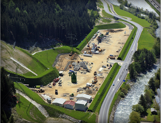
Figure 5. Construction on the Brenner Base Tunnel is currently underway.
And the last issue is actually that we have been trying to develop ideas for the reuse of excavation material. The concrete mixture must be sustainable for the next 200 years since this is the lifetime of the tunnel. We have been studying the material of the exploratory tunnel (Figure 6), especially the schists, in the central zone of the project and we were able to modify the preparation methodology and optimize the concrete mixture to re-utilize 100% of the excavation material. Five years ago, all of the geologists and specialists during the approval phase told us that the excavation material must be disposed of. So this is actually a real step forward into optimizing the project excavation.
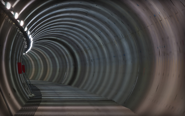
Figure 6. The completed exploratory bore for the Brenner Base Tunnel.
What is your opinion about the on-site TBM assembly of Robbins compared with the re-assembly of factory-built machines on jobsites?
From an engineering point of view we are only interested that the machine works very well on site. So we are interested to see, when the machine really starts, the performance in a certain excavation length. We are interested in the results and not so much on the specific assembly situation. There are different trade-offs: On the one hand, if you pre-assemble the machine in the production facility, this can guarantee you certain tolerances and probably certain pre-operation errors can be adjusted and finally avoided. But, the major problem is that you have to transport the semi-assembled machine on site and you have to re-assemble the machine on site again and then you have to start excavation. However, with Robbins for example, they can bring all the individual pieces on site and very often they are adjusting the machine itself directly under site conditions. It is easier, I think, to do the adjustment on site directly for specific logistics reasons. We can say that you might have more flexibility if you assemble directly on site compared with doing the assembly at the production facility.
Mexico's Crossover TBM makes its Mark for Robbins
On March 29, 2016, North America’s first Crossover TBM broke new ground in Mexico City. The 8.7 m (28.5 ft) diameter Robbins XRE™ –a cross between a rock TBM and an EPB–emerged into an intermediate shaft at Emisor Poniente (TEP) II.
The machine is undergoing some maintenance before continuing on to bore the final 3.2 km (2.0 mi) of tunnel. The customized TBM, for a consortium of Aldesem, Proacon, and Recsa, was chosen based on a number of parameters that included challenging ground conditions below an area to the west of downtown Mexico City.
The tunnel path travels through a mountain with cover as high as 170 m (560 ft), through fault zones and in a section with cover as low as 8.0 m (26.2 ft) above the tunnel crown. Much of the tunnel consists of andesite rock with bands of tuff, and softer material in fault zones as well as an 874 m (2,870 ft) long section in soft ground at the end of the tunnel.
“The geological profile of the project comprises six different lithologies, among them hard rock such as dacite. To get the best operation in both areas required use of dual mode technology such as the Crossover TBM,” said Enrique del Castillo of contractor Aldesem. The 8.7 m (28.5 ft) diameter Robbins XRE (Cross between Rock/EPB) is a design that allows for the TBM to effectively bore in both hard rock and mixed ground.
The machine setup includes a canopy drill and positioner for enhanced ground consolidation, as well as gear reducers to adjust torque and RPM based on ground conditions. The TBM, initially launched in hard rock mode, can be operated in EPB mode later on by switching out the belt conveyor with a screw and converting the cutterhead.
The Robbins Crossover machine began its journey in August 2015, and advance rates picked up quickly. Project records were set in January 2016 after the machine achieved a best day of 42.8 m (140 ft) and a best week of 185.1 m (607 ft). By mid-March the machine had bored through the first of the contact zones, a 30 m wide section of fractured and blocky rock. While the excavation through the contact zone was slow going, progress picked up again in the more competent rock. Final breakthrough is expected in autumn 2016.
Once complete, the 5.8 km (3.6 mi) tunnel will supplement an existing and overtaxed wastewater line built in the 1970s. The deep drainage tunnel will serve to prevent recurrent flooding in Valle Dorado, and will benefit the cities of Cuautital Izcalli, Tlalnepantla, and Atizapan de Zaragoza, an area with a total population of 2.1 million inhabitants.
Robbins EPB surmounts Chennai Metro Challenges
On January 27, 2016, a Robbins mixed ground EPB broke through at Chennai Metro, finishing up a challenging second drive that saw the full gamut of difficult conditions. The 1,027 m long second drive for the machine was part of Lot UAA-01 on Line 1 of the city’s metro, consisting of two parallel 1.0 km (0.6 mi) tunnels running from the Washermanpet area towards Chennai International Airport. Contractor Afcons Infrastructure Ltd. reflected on the breakthrough: “We are really proud of our executing team, who have maintained a high standard of quality. We didn’t record any water leakage or settlement at the surface, and we have demonstrated a high standard of safety in the tunnel during construction,” said Mr. Gopal Dey, Sr. Manager for Afcons.
The 6.65 m (21.8 ft) diameter Robbins EPB was designed to excavate granite, sand, silt, and clay with boulders up to 300 mm (12 inches) in diameter. The specialized design utilized a combination of 17-inch diameter disc cutters as well as soft ground tools. Small grippers located around the circumference of the machine’s shield allowed for cutterhead stabilization in harder ground, while additionally reacting the forces needed to pull the cutterhead back from the face in difficult conditions.
The TBM was launched on its initial drive in January 2012 from a 28 m (92 ft) deep starting pit. Challenges began nearly from the outset. The TBM bored into mixed face conditions that contained varying strengths of granite, from weathered to hard granite of 150 MPa (21,700 psi) UCS. The unexpectedly hard rock caused high cutter consumption rates and slowed advance.
A crew of Robbins Field Service personnel and engineers assisted Afcons in remedying the problem. Robbins India provided a geologist who carried out face mapping for the whole of the first drive, in both hyperbaric and open mode conditions on a daily basis. The data not only assisted the crew in operating the TBM, but also provided a comprehensive geological record for the second drive. With the data gleaned from the geological investigation, Robbins was able to advise Afcons on the optimal operating parameters to get through the difficult conditions, including cutterhead RPM, thrust pressure, penetration rate, and cutterhead torque. The parameters also resulted in a reduced cutter consumption rate.
Contractor Afcons was pleased with the help they received: “The Robbins Field Service team extended very good services to us, particularly in the mixed face & full face rock when they deployed their Geologist for face mapping. This helped us to understand the strata ahead of us, and based on this the TBM advance rate and operating parameters were decided,” said Mr. V. Manivannan, Executive Vice President for Afcons.
The TBM was launched on its second tunnel in February 2015. Conditions were just as difficult as the first drive, but now the team approached it with experience: “We experienced very high water pressure in this alignment, as the water table in Chennai is just 1.5 m (5 ft) underground and the strata above the crown included silty sand, clay and weathered rock. It was very important for us to maintain the earth pressure to reduce the inflow of water, and to avoid any settlement on the surface with proper grouting,” said Dey. Despite the challenges the TBM was able to complete a section below the Koovam River without any water flowing into the tunnel. The machine achieved up to 12.6 m (41 ft) in one day and 62 m (203 ft) in one week.
The TBM broke through into a receiving shaft, utilizing a unique setup for the second time that had the machine emerging under water. “These were the first breakthroughs in India under wet conditions in the retrieval shaft, which is 30 m (98 ft) below the ground level. The retrieval shaft was filled with Bentonite slurry 10 m (33 ft) from the base slab in order to arrest water entry from outside the diaphragm wall,” explained Manivannan.
The completed sections of tunnel will now be commissioned as part of Line 1, a 32.1 km (19.9 mi) long route in total with 14.3 km (8.9 mi) underground and a total of 17 stations. The southeastern Indian city of Chennai is a rapidly growing technological and industrial center with a population of more than 8.2 million people and a high need for alternate means of transportation.
Rosemont Double Shield on a roll for Robbins
In a large November 2015 ceremony attended by the mayor of Montreal, Quebec, Canada, and representatives from local media outlets, the Rosemont Reservoir tunnel construction came to a close. The challenging project gave good cause for celebration as crew members crowded around the cutterhead of the 3.0 m (9.8 ft) diameter Double Shield TBM that had emerged into an exit shaft.
Local contractor Foraction, Inc., headed the excavation of the 4.0 km (2.5 mi) long tunnel with a TBM launch in December 2014. Roger Lepinay, Equipment Manager for Foraction, Inc., praised the Robbins disc cutter wear in both limestone and harder rock formations: “I was impressed by the cutters, it was a nice surprise. They were quite long-lasting compared to other cutters I have used on jobs in the past.”
Lepinay characterized the ground as “almost ideal”, with a few difficult sections. “Below Montreal there is mostly thinly bedded limestone, with some shale and intrusive igneous rocks, mainly dykes and sills,” explained project geologist Brigitte Gagné for company Exp Service Inc. While the limestone averaged 100-150 MPa UCS, rock in the intrusives ranged from 100-300 MPa. The dykes and sills were as small as a few centimeters wide and as large as 8 to 10 m (26 to 33 ft) wide. The contractor was able to successfully navigate these sections despite the varying rock strengths. Even with geologic challenges including some water inflows and over-break in small sections, the contractor was able to achieve advance rates of up to 38 m (125 ft) per day in two shifts of 9.5 hours each. Much of the ground was self-supporting, though the contractor installed rock bolts every 2.5 m (8.2 ft) into portions of the tunnel crown, while mesh, rock bolts, and steel sheets were used in the sections of unstable rock.
The long tunnel drive at small diameter was carefully planned to optimize logistics. The contractor utilized a muck train that could accommodate two pushes worth of excavated material. The first kilometer (0.6 mi) was ventilated from the launch shaft, while three surface-driven 800 mm (32 in) diameter surveying wells at the 1, 2, and 3 km (0.6, 1.2, and 1.9 mi) marks ventilated the rest of the tunnel as the TBM progressed.
With the breakthrough, an important phase of the Rosemont Reservoir project is complete. The reservoir itself was built in 1960 to increase water supply to the city and a geotechnical study for the tunnel was carried out in 1977. However, other major infrastructure projects soon took priority and the project was placed on hold. By 2010, the population of the city had increased dramatically and problems with the existing reservoirs put the project back on the fast track. The large reservoir that sat idle for decades will now be used to improve much of the city’s water supply.
As of mid-January the contractor is working to ready the tunnel for installation of the carrier pipe, consisting of 2.13 m (84 in) I.D. pre-stressed concrete cylinder pipe (PCCP). Crews will then grout the pipe in place. There will be several more work stages to be carried out before the Rosemont Reservoir is finally reconnected to the water main network in 2019.