 Close
Close  Menu
Menu 
Project Categories: Crossover
Ohio Canal Interceptor Tunnel
Project Overview 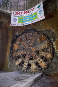
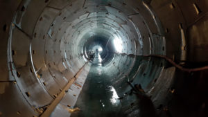
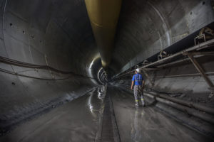
The Ohio Canal Interceptor Tunnel (OCIT) is the key component of the City of Akron’s Long Term Control Plan aimed at reducing Combined Sewer Overflows (CSOs) into the Little Cuyahoga River, and surrounding streams. Akron Waterways Renewed, is the city’s water initiative. The mission of this initiative is to promote the benefits of the OCIT and related structures and dispense knowledge about the EPA-mandated solution to clean up the city’s waterways. The 1900 m (6,200 ft) long OCIT is able to handle 1703 L (450 gallons) of CSO annually in a 8 m (27 ft) finished inside diameter tunnel. The tunnel will be able to achieve water storage and maximize conveyance and green infrastructure.
Geology
The OCIT passed through three zones or reaches that had distinctly different ground conditions. The generalized ground conditions in these reaches consisted of soft ground (Reach No. 1), mixed face conditions with soft ground overlying bedrock (Reach No. 2), and bedrock with two sections of low rock over (Reach No. 3). The rock in Reaches 2 and 3 consisted primarily of weathered shale which transitioned to shale, siltstone, and minor amounts of sandstone.
In Reach 2 there were four obstructions that were encountered within the soft ground section that consisted of natural deposited boulders. The bedrock in Reach 2 was observed to have very widely spread horizontal clay seams in the rock core.
Within Reach 3 a zone of completely weathered bedrock was encountered at the top of the bedrock surface. Very widely spread horizontal clay was also observed in the rock core, ranging from 1 to 3 inches thick along the tunnel alignment in Reach 3.
The Machine and Continuous Conveyor
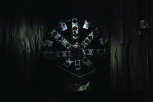
The Crossover XRE included features of EPB and Hard Rock Shield TBM types, with a versatile cutterhead design built specifically to address a common issue in mixed ground TBM tunneling: abnormal flat and multi flat cutter wear, which results in the cutter wearing flat on part of its surface. The XRE TBM cutterhead was equipped with 56 housings that could be dressed in either knife bits/rippers or 17-inch disc cutters. Due to the geological variability, it was decided that disc cutters would be beneficial from the outset, so the machine was launched with a full dressing of discs.
For boring in soft ground, the pre-torque of the cutter bearings was reduced by 25%, in order to require less rolling force for each cutter to rotate evenly. Sacrificial rippers were welded to intervene in case of ring wear greater than 15 mm (0.6 in), to avoid hyperbaric intervention in the first 491 m (1610 ft) of boring. 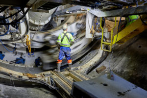
The screw conveyor was another customized component of the TBM, in a shaft-type design, 20 m (64.5 ft) long, 1.2 m (47 inches) in diameter, with a tapered front nose to 1 m (30 in).
In both rock mode and mixed ground, the auger and the casings were in contact with abrasive material, creating wear. The screw conveyor was designed for an abrasive environment, with chromium carbide wear plates and hard facing.
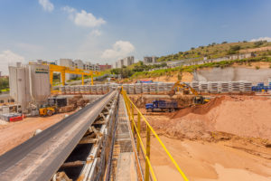
For muck removal, a Robbins Continuous Conveyor system was employed. The conveyor system consisted of a main drive, splice stand, storage unit, and advancing tailpiece, operating through several curves requiring patented self-adjusting curve idlers that adjust belt tension based on the belt load. The system discharged onto a customer-supplied overland conveyor, which delivered the muck to a large storage yard near the portal site.
Excavation
In October 2017, the TBM was launched, with a depth to invert of approximately 12 m (40 ft) through a jet grout plug installed to provide a controlled launch environment. Cutterhead clogging was a problem but was overcome easily enough. The launch of the TBM was one of the most arduous aspects of this project due to the geology of the site. The machine launched into a very short reach of 61 m (200 ft) of soft ground, which then transitioned into mixed ground for 183 m (600 ft).
While in soft ground and mixed face conditions the machine operated in closed mode, and then switched to open mode once the crews hit solid rock. The advance rates once in full-face shale rock reached a high of 34 m (111 ft) in one day (two 10-hour shifts). Continuous conveyor availability remained high throughout the bore.
With the launch, the machine was nicknamed “Rosie” in respect and honor of Rosie the Riveter, an icon representing American women who worked in factories and shipyards during World War II.
Breakthrough
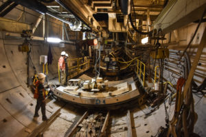
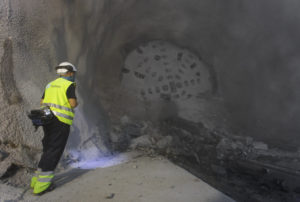
On August 29, 2018, the 9 m (30.4 ft) diameter Robbins Crossover (XRE) TBM completed its mission at the Akron Ohio Canal Interceptor Tunnel (OCIT). With tunneling complete, the machine was disassembled and removed from its retrieval shaft.
Gerede Water Transmission Tunnel
Robbins Crossover Excels in Turkey’s Most Demanding Tunnel to Date
Project Overview
The Gerede Water Transmission Tunnel is arguably one of the most difficult projects attempted in the world of tunneling. Dozens of fault zones and intense water pressures up to 20 bar are just a couple of the challenges to overcome. Prior to Robbins involvement, three standard Double Shield TBMs, originally supplied by a European manufacturer, attempted to bore the tunnel. Of the three, two became irretrievably stuck following massive inflows of mud and debris. In 2016, a Robbins Crossover XRE machine was launched to excavate the final 9 km (5.6 mi) of the 31.6 km (19.6 mi) long water supply tunnel. Due to severe and chronic droughts in the capital city Ankara, the water line has been deemed a national priority. Once complete, the supply line will draw water from the Gerede River and will be the longest water tunnel in Turkey.
Geology
Turkey is in a tectonically active region controlled on a grand scale by the collision of the Arabian Plate and the Eurasian Plate. At a more detailed level, a large piece of continental crust almost the size of Turkey, called the Anatolian block, is being squeezed to the west. The block is bounded to the north by the North Anatolian Fault and to the south-east by the East Anatolian fault. Geology in the fault zones tends to be highly variable and unstable.
At Gerede, the Anatolian Fault Zone certainly presented many obstacles. Geologic testing and borehole samples showed a mix of volcanic rock including tuff, basalt, and breccia, giving way to sedimentary formations like sandstone, shale, and limestone, all punctuated by fault zones that contained clay and alluvium. The Crossover machine also faced an aquifer system that caused high-pressure water inrushes of 26 bar.
Machine Design
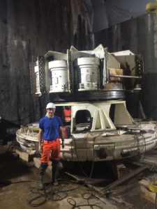
Due to the geology, the Gerede machine required a convertible cutterhead optimized for hard rock. The cutterhead was designed for ease of conversion between hard rock and EPB modes, and cutter housings can be fitted with either disc cutters or tungsten carbide tooling. In addition, the cutterhead is designed to operate in a single direction. The setup, which is used on all XRE machines, allows for greater efficiency while excavating, with lower power requirements and less chance of regrind. To cope with difficult ground, the Gerede machine was also equipped with special gearing.
In order to protect the machine from the expected high water pressure, an extensive sealing system was put into place. Around the main bearing, there is an outer row of six seals and an inner row of three seals. Between each seal, the cavity is filled with grease to ensure a constant pressure. In the event that the machine is shut down and an inrush of water overtakes the machine, a pressure sensor will detect this presence of water and flush the seal system with grease in order to continually protect the seals. The articulation joint and the gripper and stabilizer shoes are sealed off in the same manner.
Perhaps one of the most important parts of the Gerede TBM design is the screw conveyor. Because of the potential for massive amounts of water, the machine must have a sealed screw conveyor. However, running rock through a screw conveyor can be highly abrasive. To account for potential wear, the screw was been designed with replaceable wear plates along its entire length. The screw itself was also made up of short sections that can be removed and replaced if needed. Multiple access hatches were included for maintenance of the wear plates, while two large, removable outer casings could accommodate the change-out of entire screw sections.
Due to the unpredictable ground conditions, it was necessary to detect and grout off zones of concern wherever possible in order to protect the machine from loose ground and water pressure. The machine utilized a standard array of twelve Ø100 mm ports angled at 7° that are equally spaced around the rear shield. Each port was sealed by a ball valve until it was needed for probing. Ten of the same-sized ports were also located straight through the forward shield for probing and grouting. Six additional hatches were built into the pedestal at the front of the machine. The hatches could be used with a pneumatic percussive drill in the center section of the cutterhead.
Excavation
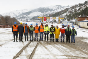
The Robbins XRE TBM was launched in summer 2016, using some components from the original Double Shield TBM back-up, as well as the remaining segments being stored for the project. Crews excavated a bypass tunnel to one side of the stuck Double Shield TBMs and the Robbins TBM components were walked in through the south portal. The machine was assembled using Onsite First Time Assembly (OFTA) in an underground launch chamber. Water flow made it difficult to get the materials to the machine, but this was overcome by designing custom flat cars equipped with hydraulic lifts to transport bigger sections of the TBM through the tunnel to the build chamber.
The Robbins machine began boring at a slight angle to the rest of the tunnel, bypassing the stuck machine before gradually meeting up with the original tunnel alignment. The machine was required to be used in EPB mode as it encountered water pressures up to 26 bars, alluvium, flowing materials, and clay. Water pressure was lowered by draining the ground water through the rear shield probe drill ports, which were equipped with normally-closed ball valves. Probe drilling became routine after advancing 50 meters (164 feet) past the section that buried the original Double Shield TBM. During its bore the TBM encountered a total of 48 fault zones. Despite the constraints of the difficult geological conditions and the time it took to reach the TBM within the tunnel, crews achieved a best day of 29.4 m (29.4 m (96.5 ft), best week of 134.6 m (441.6 ft) and a best month of 484 m (1,588 ft).
Breakthrough
 Excavation of Turkey’s longest water tunnel came to an end on December 18, 2018. With tunneling complete, the pipeline opened in March 2019. The tunnel will convey water from the Gerede River to Çamlıdere Dam, which provides potable water for the Ankara city water system.
Túnel Emisor Poniente (TEP) II
Project Overview
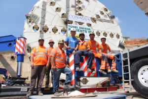 A Robbins Crossover (XRE) TBM was chosen to bore a 5.8 km (3.6 mi) tunnel as part of Mexico City’s wastewater management efforts, making it the first Crossover machine to bore in North America. The 8.7 m (28.5 ft) diameter machine includes features of both a hard rock single shield and an EPB in order to “cross over” into vastly different types of ground. Once complete, the tunnel will prevent flooding in urban areas and will convey sewage to the area’s first wastewater treatment plant, affecting the lives of 2.1 million people.
Geology
The tunnel path travels through a mountain with cover as high as 170 m (560 ft), through fault zones and in a section with cover as low as 8.0 m (26.2 ft) above the tunnel crown. Much of the tunnel consists of andesite rock with bands of tuff, and softer material in fault zones as well as an 874 m (2,870 ft) long section in soft ground at the end of the tunnel.
Machine Design
 The Robbins XRE TBM features components like a convertible cutterhead that can be changed from a Hard Rock to EPB design, a removable belt conveyor and screw conveyor, and multi-speed gearboxes to increase torque for tunneling through difficult ground. Breakout torque is one way that the shielded TBM can propel itself through fracture zones without becoming stuck—multi-speed gear boxes can be activated to achieve high torque at a low speed, similar to how an EPB operates. With multi-speed gear boxes, the cutterhead can be freed in bad ground where it might otherwise become stuck. In hard rock, the TBM can operate in a standard low torque, high RPM mode.
The Crossover XRE has other strategies in its arsenal to deal with difficult ground. The unique TBM was designed to bore below several valleys with expected water inflows. In the event of a high water inflow, a guillotine gate located on the muck chute is able to seal off the mixing chamber from the rest of the machine. In this way the TBM can passively hold high water pressures while the crew takes measures to dewater and consolidate ground.
The machine is equipped with continuous probe drilling, with a wide drilling range to investigate ground ahead of the machine. In addition to the standard probe drill, a canopy drill provides another ring for grout drilling or forepoling close to the cutterhead and in the top 120 degrees of the tunnel, while a second probe/grout drill is located further back on the machine, allowing two different patterns of holes.
Excavation
 The Crossover machine was launched in August 2015 in a hard rock configuration and mounted with 20-inch diameter disc cutters—a risky move given that the first sections of tunnel were in softer soils before the TBM hit more solid rock. The machine’s advance rates picked up quickly, with project records set in December, and again in January after the machine achieved a best day of 42.8 m (140 ft) and a best week of 185.1 m (607 ft).
Early in 2016 the TBM hit the first of several contact zones, a 30 m (98.4 ft) wide fault of fractured and blocky rock. While the excavation through the contact zone was slow going, progress picked up again in the more competent andesite rock. After an intermediate breakthrough in March 2016 into an 80 m (262.5 ft) deep shaft followed by inspection and maintenance, the TBM continued on.
By June 2016, the TBM was boring in fairly competent rock and had achieved two national records for TBM advance—one for excavating 57 m (187 ft) in one day and another for boring 702.2 m (2,303.8 ft) in one month.
While boring in fractured andesite rock in autumn 2016, the TBM encountered a naturally occurring cavern believed to be the result of either a rock fall in a transition zone, or an old, underground lake body that had eroded the rock away. The cavern was approximately 90 cubic meters in size, including about 57 cubic meters of unstable floor area. The TBM was stopped and immediate measures were taken to fill the cavern.
Changing Modes
 By the end of October 2016, the TBM had reached the final section of soft ground. In this final zone of low cover, the distance from the top of the tunnel to the surface is less than 1.5 times the machine diameter, and the ground has the consistency of reconsolidated soil. The residential area meant that subsidence had to be kept to a minimum, and the decision was taken to convert the Crossover machine to EPB mode.
Conversion of the TBM to EPB mode required multiple steps. The conversion process started with the modifications of the cutterhead, adding the piping for the new foam lines, changing the hard rock bucket lips into the EPB soft ground scrapers, and removing the muck buckets characteristic of a hard rock TBM. The removable plates on the cutterhead were changed to alter the opening ratio from Hard Rock optimized to EPB optimized (from 7.9% to 18.95%). Other steps include installing mixing bars into the bulkhead, switching out the TBM belt conveyor to a screw conveyor, altering the fluid system for EPB additives, and installing tails seals and articulation seals for pressurized boring.
 The machine was completely converted and ready to bore at the start of 2017. The machine started its latest section with about 18 m (59 ft) of cover, which was reduced due to the ground slope to just 12 to 14 m (39 to 46 ft). By March 2017, the TBM had performed well, with just 517 rings (about 775 m, 2.543 ft) left to bore. The TBM’s best day of production in soft ground was 13 rings (19.5 m, 64 ft) in only one 12-hour shift—impressive results despite the limited boring hours due to the residential area above. Final breakthrough occurred in late May 2017.
Kargi Hydroelectric Project
Robbins Double Shield TBM Overcomes Challenging Conditions and Spurs the Design of Crossover TBMs
Project Overview
 Driven through a mountainside with 600 m (1,968 ft) of cover in Central Turkey, the Kargi Kizilirmak Hydroelectric Project is one of the most challenging tunneling projects ever completed in the region. A 10-m (32.8 ft) diameter Double Shield TBM was supplied to contractor Gülermak to bore the headrace tunnel that would divert water from the dam to the powerhouse. The entire tunnel, with both TBM and drill and blast portions, is 11.8 km (7.3 mi) in length. The project generates 470 GWh of power annually for project owner Statkraft, an amount sufficient enough to supply approximately 150,000 homes. The extremely challenging ground conditions of this project made it necessary for the machine to be modified in-tunnel. The results of which largely contributed to the creation of the Crossover machines used today.
Geology
The expected geology along the tunnel alignment consisted of Kirazbasi complex Kargi ophiolites (including sandstone, siltstone and marl) for the initial 2,300 meters (7,545 ft), followed by 1,000 meters (3,280 ft) of Kundaz metamorphites (including marble, metalava and metapelite), and the remaining 8,500 meters (27,887 ft) consisted of Beynamaz Volcanites (including basalt, agglomerates and andesite). The anticipated strength of the rock was up to 140 MPa. Multiple fault zones and transition zones added to the complexity of the geological conditions.
Launch
Almost immediately after launch in early 2010, the machine encountered geology that was substantially more problematic that was described in the geological report. The geology consisted of blocky rock, sand, and clays. 80 meters (262 ft) into the bore the TBM became stuck in a section of collapsed ground. As a countermeasure that was immediately put into place to avoid the cutterhead becoming stuck in the blocky material, crews began boring half strokes and half resets. Despite these measures, the machine encountered a section of extremely loose running ground with high clay content. Another collapse occurred in front of the cutterhead and the weight of the material trapped the cutterhead.
After assessing all the available options, it was decided that a bypass tunnel would be required. Robbins Field Service assisted Gülermak with bypass tunnel design and work procedures to free the cutterhead and stabilize the disturbed ground. Blasting techniques were ruled out due to concern over further collapses caused by blast induced vibration; hence, the excavation was undertaken using pneumatic hand-held breakers. Hopes that the section of bad ground would be an isolated occurrence were quickly proved wrong, and the actual complexity of the geology became apparent. Six more tunnels were needed within the first 2 km (1.2 mi) of tunneling.
Both the contractor and manufacturer worked together to develop and improve bypass tunneling and hand tunneling techniques, resulting in an average bypass tunnel construction time of just 14 days. All tunnels were completed safely and in a timely manner, though there were of course significant delays associated with the downtime. Despite the setbacks of these multiple events, the TBM did succeed in crossing numerous faulted sections that would have trapped a machine with less power. Bypass tunneling was successfully completed and at that point the section of bad ground was believed to be an isolated one.
The Beginnings of the Crossover TBM
 In order to improve progress in the difficult conditions, the contractor, owner, consultants, and Robbins engineers worked together to generate solutions. The contractor, with the assistance of the field service team, installed a Robbins custom-built canopy drill and positioner to allow pipe tube support installation through the forward shield. Drilled to a distance of up to 10 m (33 ft) ahead of the cutterhead, 90 mm (9 cm) diameter pipe tubes provided extra support across the top 120 to 140 degrees at the tunnel crown. Injection of resins and grout protected against collapse at the crown while excavating through soft ground. As a result of successful use of the probe drilling techniques, Gülermak was able to measure and back-fill cavity heights above the cutterhead in some fault zones to over 30 m (98 ft) and, in addition, was able to help detect loose soil seams and fractured rock ahead of the face.
To further mitigate the effects of squeezing ground or collapses, custom-made gear reducers were ordered and retrofitted to the cutterhead motors. They were installed between the drive motor and the primary two-stage planetary gearboxes. During standard boring operations the gear reducers operate at a ratio of 1:1, offering no additional reduction and allowing the cutterhead RPM to reach design speeds for hard rock boring. When the machine encountered loose or squeezing ground the reducers were engaged, which resulted in a reduction in cutterhead speed but the available torque was increased by nearly double. The net effect of the modifications allowed the Double Shield TBM to operate much like an EPB in fault zones and squeezing ground with high torque and low RPM—these methods effectively kept the machine from getting stuck. In addition, short stroke thrust jacks were installed between the normal auxiliary thrust to double total thrust capabilities.
The TBM design changes gleaned from Kargi were not considered to be isolated, and immediately began to inform the design of Robbins’ new line of dual-mode type machines, termed Crossover TBMs. Crossover TBMs are also called hybrid or Dual Mode machines, and are able to “cross over” into distinct types of geology. Crossover TBMs feature aspects of two TBM types, and are ideal for mixed ground conditions that might otherwise require multiple tunneling machines.
Innovative Results
 Despite the slow progress initially, the Robbins Double Shield TBM made some remarkable advances once modifications were in place, which essentially made it a Double Shield TBM with Crossover features. An advance rate of 600 m (1,986 ft) in one month was achieved in March 2013 and a project best of approximately 723 m (2,372 ft) was achieved in spring 2014, including a daily best of 39.6 m (130 ft) in April 2014. In so doing the TBM significantly outperformed a drill and blast heading progressing from the opposite end of the tunnel. Crews at that heading progressed in relatively good ground conditions for 4 km (2.5 mi), where they achieved advance rates of nearly 300 m (984 ft) per month. The TBM bored 7.8 km (4.8 mi) of the tunnel in total, making its final breakthrough in July 2014.
Grosvenor Decline Tunnel
First TBM to be used for Mining Tunnels in Queensland
Project Overview
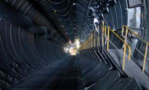
 The Grosvenor Mine, a greenfield coal operation, was the first to utilize TBM technology for mining tunnels in Queensland. Owner Anglo American opted for an 8 m (26 ft) diameter Robbins Dual Mode “Crossover” TBM and continuous conveyor system, which was assembled on location using Onsite First Time Assembly (OFTA) with onsite support from Robbins’ experienced Field Service team. The Crossover XRE TBM was picked over the traditionally-used roadheader method for several reasons, including excavation speed and tunnel maintenance. The machine bored two decline access tunnels at grades of 1:6 and 1:8, one for conveyors and another for people and equipment.
Geology
Ground conditions varied throughout each tunnel. Both drifts contained geology consisting of mixed soil and rock conditions, with the first 300 m (984 ft) or so of each tunnel containing the majority of the mixed ground such as soft clays and soils.
Machine Design
OLYMPUS DIGITAL CAMERA
The machine’s Crossover capabilities enabled it to operate in both hard rock and mixed ground. In addition, the TBM was required to operate in gaseous conditions. The unique TBM design included a cutterhead capable of interchanging hard rock and soft ground cutting tools, a two-stage center-mounted screw conveyor, a “quick removal” shield system, and flame-proof machine components due to the possibility of methane gas in the underground environment. A machine with EPB capabilities was chosen not only due to the presence of softer ground, but also to contain the methane gas where it could then be diluted or safely removed from the tunnel.
Excavation and Breakthrough
Construction on the Grosvenor project began in July 2012. The first of the decline tunnels, for conveyors, was excavated between the end of December 2013 and the beginning of May 2014, after achieving advance rates of up to 90 m (295 ft) per week. The Quick Removal System was a success, allowing the TBM inner core to be retracted back to the surface from a 160 m (525 ft) depth using specially designed transport dollies. In order to transport the machine to the next tunnel 2 km (1.2 mi) away, the TBM had to be split into two sections and required a large 600 metric ton lift.
 The machine was re-commissioned for the men & materials tunnel with a new set of shields, and commenced boring in November 2014. Excavation was completed in 88 days at an average of 10.9 m (35.7 ft) per day, with a best day of 25.2 m (82.7 ft). The TBM averaged 70 m (229.7) a week, about 14 times faster than a roadheader. The bore itself was similar to the first, with few challenges encountered other than elevated methane gas levels that required several temporary stoppages in order to safely remove the gas from the tunnel. Final breakthrough was reached on February 9, 2015. Upon completion of the second tunnel, the machine shields were again left in place to provide continuous support.
Recent Posts
- Cooperative Innovation at the Manhattan Tunnel Project: Digger Shields with Expandable Segments to Excavate Complex Fill
- Robbins celebrates TBM acceptance for Ellicott City North Tunnel
- Huge Robbins Slurry TBM breaks through in Hiroshima
- Robbins TBMs break through at Delhi Metro DC-07 Project
- RETC 2025