 Close
Close  Menu
Menu 
Project Categories: Double Shield TBM
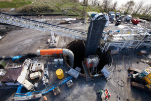
Bheri Babai Diversion Multipurpose Project
Project Overview
The Bheri Babai Diversion Multipurpose Project (BBDMP) is one of Nepal’s 11 National Pride Projects. These projects are prioritized plans sanctioned by the Government of Nepal to further develop the mostly rural country. The tunnel irrigates 60,000 (231.7 SM) hectares of land in the southern region of Nepal, and benefits at least 30,000 households. The tunnel also diverts 40 cubic meters (10,567 gal) of water per second from Bheri River to Babai River under a head of 150 m (492.1 ft) using a 15 m (49.2 ft) tall dam, to provide year-round irrigation to the surrounding Banke and Bardai districts. Hydroelectricity is another benefit provided with a generating capacity of 48 MW.
Geology
For this project, the difficult geology of the Siwalik Range, part of the Southern Himalayan Mountains, was much easier than anticipated. The Siwalik Range consists mainly of sandstone, mudstone, and conglomerate. Squeezing ground, rock instability, water inflows and fault zones were also in the mix.
Machine Design
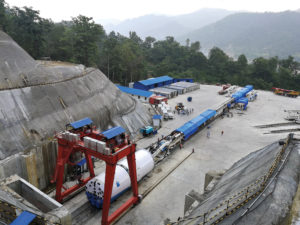
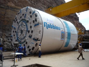
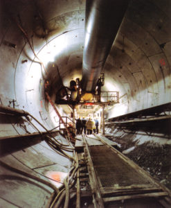
Contractor COVEC Nepal prepared for the challenges associated with tunneling in the tough geology by procuring a custom-designed 5.06 m (16.6 ft) diameter Robbins Double Shield TBM—the first TBM to excavate in Nepal. This TBM bored 12,210 m (40,060 ft) under a mountain range with maximum rock cover of 820 m (2690 ft) and altitude gains of 152 m (499 ft). The machine also had to pass through the Bheri Thrust Zone, a 400 (1312 ft) to 600 m (1969 ft) wide fault which contained clay and water ingress.
Additional features, known as Difficult Ground Solutions (DGS), were built into the design that prevented the machine from becoming stuck while navigating the possible squeezing ground and water ingress:
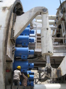
- Stepped shield: A tapered shield that stepped down to smaller diameters, from the head to the tail, opened the annular gap at the tail of the machine. This allowed for more space around the machine for the ground to contract and lessened the chance of the shield becoming stuck.
- Probe Drilling: By probing drilling in front of the machine, the upcoming ground conditions and water content could be checked. If poor ground was found, grouting could take place to consolidate the zone ahead of the machine. This created a solid plug to bore through. Because high water was planned for, this machine was equipped with several probe drilling locations. 14 ports in the gripper shield at seven degrees were in line with a rear probe on a ring. There were also eight ports in the forward shield at seven degrees that could be drilled by hand. In case of large amounts of water, this array of drilling and grouting gave a full 360 degrees of coverage.
- Shield Lubrication: Although this system was not used, ports were designed radially into the gripper shield that could be used to pump bentonite or other additives to the shield skin to help lubricate the surface and keep the machine moving in squeezing ground.
- Forepoling: Ports were also designed into the forward shield for the option of adding a forepoling drill in the upper forward shield area. This feature would be able to drill holes at 22 degrees, where poles could be inserted into the ground above the machine in an overlapping pattern to stabilize the ground.
Excavation
On October 16, 2017, boring officially commenced. After the initial start-up period, excavation rates exceeded and often doubled the estimated rates. The TBM averaged over 700 m (2,297 ft) per month, with a top excavation rate of 1,202 m (3,944 ft) in one month. Progress was exponential and the project was completed a full year earlier than planned. The ground conditions were better than predictions showed, with 92 percent of the tunnel lined using Type 1 segments (less reinforcement) and only 8 percent of the tunnel requiring more heavily reinforced Type 2 segments. Prior to tunneling predictions stated as much as 26% of the tunnel would require Type 2 segments.
The navigation of the Bheri Thrust Zone was successful. Due to the effective countermeasures taken by the contractor, the fault zone was navigated safely and without delay. The Horizontal Sonic Profile Method (HSP) was introduced to predict geological conditions 100 m (328 ft) ahead of the tunnel face. The prediction results were verified with probe drilling. The TBM passed through the fault zone safely and smoothly within only one week without any challenges. 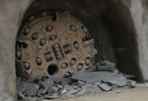
Excavation Challenges
There were several challenges during excavation, which the crew maneuvered successfully. For instance, on December 27, 2017, large amounts of water began pouring from the 8 o’clock position more than 1 km into tunneling. While the machine advanced the ingress of water shifted to the 11 o’clock position. The contractor thought it was unnecessary to carry out grouting for water plugging, because the section was mainly composed of sandstone and the rock strength was relatively high. However, the method of of slowed excavation, enhanced pumping and drainage, was not sufficient and as inflows intensified back-filling and plugging were adopted.
A second occurrence of high water happened January 6, 2018 a few hundred meters later. Water entered at the 12 o’clock position at an approximate rate of greater than 2000 l/min. The contractor again adopted methods of slow excavation, enhanced pumping and drainage, and intensified back-filling and plugging. The section was in sandstone stratum with excellent stability, and the ingress of water came through fissures in the rock. The determination was there were minimal risks of the TBM being stuck or buried. The resolution was to slowly bore through the water without any drilling or grouting to stop the water.
Not all challenges were water-related; on October 10, 2018 the machine became stuck and could not progress more than 8 km (5 mi) into tunneling. Prior to this stage, the axis of the tunnel was perpendicular to the grain of the rock, a favorable condition for tunneling. However, ground conditions started to change, and the grain became nearly parallel to the tunnel axis. The geological conditions of the tunneling face were soft on the left-hand side and harder on the right-hand side, so the machine alignment became difficult to control. The machine became lodged in place. A high thrust of 18,500 kN (9,517.2 m/s) was exerted and was not able to move the machine. To move the machine, a bypass passage was excavated from the right side of the telescopic section up to the cutterhead. It was cleared out from the 5 o’clock position to the 12 o’clock position. A thrust of 10,000 kN (5,144 m/s) was applied and the machine was able to start boring again. The bypass was completed, and the machine was moving again in just five days.
Just a few meters later at the 8.6 km (5.3 mi) mark the cutterhead became jammed. Loosely cemented sandstone and high-pressure water ingress around the 11 o’clock position triggered an over-break at the left crown area and jammed up the cutterhead. To control the water ingress, 1287 kg (2837 lbs) of polyurethane was injected through a 16 m (52.5 ft) deep probe hole. This almost completely stopped the water. A torque of 440 kNm was then applied to the cutterhead and it was able to become dislodged. 
Breakthrough
In April 2019, the Robbins Double Shield TBM defied the astoundingly difficult geology of the Himalayas and broke through about a year ahead of the overall project schedule, and seven months faster than the TBM tunneling schedule.
Various reasons led to the excellent performance at this site. The site staff maintained the machine daily and were extremely vigilant with their cutter changing standards. Logistics were a key to the advance rates being high and the favorable geology with less than expected water in the fault zones led to the success. This project opened the Nepalese tunneling industry for future TBM excavations in Himalayan geology.
Great Hydro Network
Three Double Shield TBMs tunnel on a Grand Scale
Project Overview
 At 5,464 km long, the Yellow River is the second longest in China and provides water to over 12 percent of the country’s 1.4 billion people. Its reach falls short, however, in chronically dry Shanxi Province—a region that only receives about 473 mm of rainfall annually, and has in recent years experienced severe droughts coupled with rapid economic growth.
Sprawling equally long at thousands of kilometers, the province’s Great Hydro Network (GHN) is a mind-boggling feat of human engineering in the making. The network of tunnels will source water from the Yellow River to benefit up to 24 million people in the drought-ridden region. Once complete the tunnels will supply 2.3 billion cubic meters of water per year, improving both capacity and reliability of water supply.
Tunnels throughout the GHN project are being excavated mostly by drill & blast, with four designated TBM-driven tunnels. About half of all the tunnels under construction are very deep underground. The terrain and geological structure in the area is complex; some tunnels cross coal seams and below protected areas, underground springs and other unique geological structures. The tunnels carry construction risks including methane gas, groundwater and rock bursting.
Robbins has supplied three Double Shield machines on various lots. Contractor China Railway 18 Bureau Group Co. Ltd. is responsible for Tunnel 1 (T1), a 26 km long drive through limestone, dolomite, mudstone, amphibolite, and gneiss. Tunnels 2 and 4 (T2 and T4) are using 5.0 m and 4.2 m Double Shields, respectively, on 25 km and 15.6 km long drives. Both sites are operated by Shanxi Hydraulic Construction Engineering Bureau. Tunnel 3 (T3) is using a TBM from another manufacturer.
Geology
All three Robbins TBM-driven tunnels are located in Class III to Class V rock, and excavation was expected to be challenging from the outset. In particular the rock at T4 tested as over 27% Class V and nearly 23% softer soils, with just 36% of the tunnel in Class III rock.
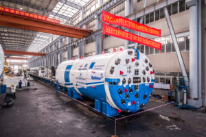
Rugged TBM Design
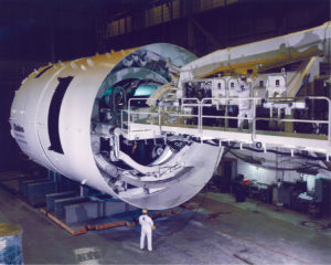
 The trio of TBMs have been designed to meet the geological challenges and long tunnel lengths. All three machines were assembled at Robbins China in Shanghai, then reassembled at the jobsites. The TBMs were built with components from Italy, Germany, Switzerland, China, and the U.S.
The machines were optimized to transport large segments quickly and safely into position to form a segment ring. The hexagonal segments are built in rings of four, each 1.2 m long. No steel reinforcement is included in the design, but gaskets between each segment help to seal them. Afterwards pea gravel is pumped into the annulus through a port in the segments to backfill voids, while a layer of grout seals them into place.
The TBMs have a uniquely long back-up system design due to the inclusion of redundant support systems– each machine is trailed by between 45 and 50 decks. Each deck is 6 to 10 m long. The redundant systems include different grout systems and at least one additional pea gravel system. This was done if one system needs maintenance or is shut down, so that the contractor can continue to bore and not affect the production of the entire line. Additional extras include redundant air compressors, as well as a rescue chamber, cafeteria, and toilet. A specialized car mover on the back-up allows two empty muck cars to be brought in with each supply train. The cars can be slid into place without needing a locomotive so that downtime in the long tunnel is minimized. The two extra muck cars have enough capacity for about two machine pushes or five rings, and can be pulled out with the next muck train.
The different diameters of the machines also necessitated unique design features. On all of the machines, squeezing the internal elements, particularly the hydraulics, into a small diameter was a challenge. The T1 and T2 machines, at 5.06 m in diameter, were able to use conventional torque cylinders in their design. The T4 machine, however, at just 4.16 m in diameter, required a redux of an old design—the lattice cylinder arrangement. The design is reminiscent of earlier Double Shield designs and offers a distinct advantage for machines less than 6 m in diameter: space. Torque arms normally occupy a large amount of space on Double Shield TBMs, and the design opens up more area to position the motors on smaller machines. It also leaves the invert open, which can aid in maintenance such as cutter changes.
Excavation and Breakthrough
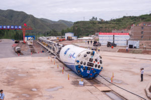
T4
The small Double Shield for T4 was the first to launch in summer 2014. The machine began boring in two eight-hour shifts, with a third 8-hour shift dedicated for maintenance. The vast jobsite covers an area of 133 square kilometers and employs an army of workers. Obstacles presented themselves nearly from the outset, as ground changed quickly between soft, weak rock and hard, abrasive rock—a condition that caused frequent cutter changes. Clay clogged the cutterhead, while water inflows occurred from a lake overhead. Despite this, the machine achieved its best monthly advance of 840 m in April 2016, and by spring 2017 had excavated more than 70% of its tunnel. This machine along with T2 completed its epic bore at China’s Great Hydro Network in 2019.
T1
The machine at T1 was the next to launch in early 2015—the assembly of which was a challenge due to timing. Winter temperatures reached -25℃ while assembling, testing and launching the TBM. Heating equipment was employed and a greenhouse was installed to keep the whole TBM warm. With those strategies the TBM testing and launch ran smoothly. Since startup, the TBM has encountered very hard rock–up to 160 MPa in some areas and progress has been slow. In areas of good ground the machine has achieved as much as 1,402 m per month and as of spring 2017 the TBM had excavated about 36% of the total tunnel length.
T2
The last of the machines, for T2, was launched in spring 2015. About 320 people work and live on the jobsite that covers 20 square kilometers. The T2 machine experienced similar varying ground conditions to those at T4, vacillating between soft rock and hard, abrasive rock. Water inrushes have been encountered multiple times and have slowed down the excavation speed. Polyurethane grouting is being done to control the water inflows. The TBM has been able to achieve up to 720 m in one month, and as of Spring 2017 had excavated more than two-thirds of the total tunnel length. This machine along with T4 completed its epic bore at China’s Great Hydro Network in 2019.
Updates of this project will be posted as boring continues.
Kargi Hydroelectric Project
Robbins Double Shield TBM Overcomes Challenging Conditions and Spurs the Design of Crossover TBMs
Project Overview
 Driven through a mountainside with 600 m (1,968 ft) of cover in Central Turkey, the Kargi Kizilirmak Hydroelectric Project is one of the most challenging tunneling projects ever completed in the region. A 10-m (32.8 ft) diameter Double Shield TBM was supplied to contractor Gülermak to bore the headrace tunnel that would divert water from the dam to the powerhouse. The entire tunnel, with both TBM and drill and blast portions, is 11.8 km (7.3 mi) in length. The project generates 470 GWh of power annually for project owner Statkraft, an amount sufficient enough to supply approximately 150,000 homes. The extremely challenging ground conditions of this project made it necessary for the machine to be modified in-tunnel. The results of which largely contributed to the creation of the Crossover machines used today.
Geology
The expected geology along the tunnel alignment consisted of Kirazbasi complex Kargi ophiolites (including sandstone, siltstone and marl) for the initial 2,300 meters (7,545 ft), followed by 1,000 meters (3,280 ft) of Kundaz metamorphites (including marble, metalava and metapelite), and the remaining 8,500 meters (27,887 ft) consisted of Beynamaz Volcanites (including basalt, agglomerates and andesite). The anticipated strength of the rock was up to 140 MPa. Multiple fault zones and transition zones added to the complexity of the geological conditions.
Launch
Almost immediately after launch in early 2010, the machine encountered geology that was substantially more problematic that was described in the geological report. The geology consisted of blocky rock, sand, and clays. 80 meters (262 ft) into the bore the TBM became stuck in a section of collapsed ground. As a countermeasure that was immediately put into place to avoid the cutterhead becoming stuck in the blocky material, crews began boring half strokes and half resets. Despite these measures, the machine encountered a section of extremely loose running ground with high clay content. Another collapse occurred in front of the cutterhead and the weight of the material trapped the cutterhead.
After assessing all the available options, it was decided that a bypass tunnel would be required. Robbins Field Service assisted Gülermak with bypass tunnel design and work procedures to free the cutterhead and stabilize the disturbed ground. Blasting techniques were ruled out due to concern over further collapses caused by blast induced vibration; hence, the excavation was undertaken using pneumatic hand-held breakers. Hopes that the section of bad ground would be an isolated occurrence were quickly proved wrong, and the actual complexity of the geology became apparent. Six more tunnels were needed within the first 2 km (1.2 mi) of tunneling.
Both the contractor and manufacturer worked together to develop and improve bypass tunneling and hand tunneling techniques, resulting in an average bypass tunnel construction time of just 14 days. All tunnels were completed safely and in a timely manner, though there were of course significant delays associated with the downtime. Despite the setbacks of these multiple events, the TBM did succeed in crossing numerous faulted sections that would have trapped a machine with less power. Bypass tunneling was successfully completed and at that point the section of bad ground was believed to be an isolated one.
The Beginnings of the Crossover TBM
 In order to improve progress in the difficult conditions, the contractor, owner, consultants, and Robbins engineers worked together to generate solutions. The contractor, with the assistance of the field service team, installed a Robbins custom-built canopy drill and positioner to allow pipe tube support installation through the forward shield. Drilled to a distance of up to 10 m (33 ft) ahead of the cutterhead, 90 mm (9 cm) diameter pipe tubes provided extra support across the top 120 to 140 degrees at the tunnel crown. Injection of resins and grout protected against collapse at the crown while excavating through soft ground. As a result of successful use of the probe drilling techniques, Gülermak was able to measure and back-fill cavity heights above the cutterhead in some fault zones to over 30 m (98 ft) and, in addition, was able to help detect loose soil seams and fractured rock ahead of the face.
To further mitigate the effects of squeezing ground or collapses, custom-made gear reducers were ordered and retrofitted to the cutterhead motors. They were installed between the drive motor and the primary two-stage planetary gearboxes. During standard boring operations the gear reducers operate at a ratio of 1:1, offering no additional reduction and allowing the cutterhead RPM to reach design speeds for hard rock boring. When the machine encountered loose or squeezing ground the reducers were engaged, which resulted in a reduction in cutterhead speed but the available torque was increased by nearly double. The net effect of the modifications allowed the Double Shield TBM to operate much like an EPB in fault zones and squeezing ground with high torque and low RPM—these methods effectively kept the machine from getting stuck. In addition, short stroke thrust jacks were installed between the normal auxiliary thrust to double total thrust capabilities.
The TBM design changes gleaned from Kargi were not considered to be isolated, and immediately began to inform the design of Robbins’ new line of dual-mode type machines, termed Crossover TBMs. Crossover TBMs are also called hybrid or Dual Mode machines, and are able to “cross over” into distinct types of geology. Crossover TBMs feature aspects of two TBM types, and are ideal for mixed ground conditions that might otherwise require multiple tunneling machines.
Innovative Results
 Despite the slow progress initially, the Robbins Double Shield TBM made some remarkable advances once modifications were in place, which essentially made it a Double Shield TBM with Crossover features. An advance rate of 600 m (1,986 ft) in one month was achieved in March 2013 and a project best of approximately 723 m (2,372 ft) was achieved in spring 2014, including a daily best of 39.6 m (130 ft) in April 2014. In so doing the TBM significantly outperformed a drill and blast heading progressing from the opposite end of the tunnel. Crews at that heading progressed in relatively good ground conditions for 4 km (2.5 mi), where they achieved advance rates of nearly 300 m (984 ft) per month. The TBM bored 7.8 km (4.8 mi) of the tunnel in total, making its final breakthrough in July 2014.
Black River Tunnel
Onsite Assembly on the Banks of the Black River
Project Overview
 In 2000, the Ohio EPA ordered the City of Lorain to address overflows that violated the City’s National Pollutant Discharge Elimination System (NPDES) permit. After studying options, including the construction of an equalization basin in downtown Lorain, a deep tunnel option was selected. In order to construct the tunnel, the city required the assistance of a USD $65.87 million loan from the Water Pollution Control Loan Fund through Ohio EPA’s Division of Environmental and Financial Assistance. The major components of the Black River Tunnel include the launch shaft and reception shaft – approximately 11 m (36 ft) in diameter and 50 m (165 ft) deep – and the main 1.7 km (1.0 mi) long tunnel with a finished diameter of 5.8 m (19 ft). The project route runs along city property roughly parallel to the Black River, beginning at the launch shaft near the Black River Wharf and terminating near the Black River Wastewater Treatment Plant.
Geology
Ground conditions consisted of soft Cleveland shale, at times layered and laminated in the tunnel crown area.
Onsite First Time Assembly
 The mammoth 7.0 m (23 ft) diameter Double Shield machine was built using Onsite First Time Assembly (OFTA)–a Robbins-developed method that saves contractors in shipping time, costs, and man-hours worked. Using the OFTA approach, individual systems are tested prior to delivery but the machine is never fully assembled in the shop. Robbins field service technicians work on location with the contractor to assemble the machine and provide support. Launch of the TBM took place on November 18th, 2013 — approximately three months after assembly began.
Excavation and Breakthrough
Construction of the main tunnel began in late autumn 2013 with both the Double Shield TBM and continuous conveyor system running at the site. Robbins supplied an in-tunnel continuous conveyor system and space-saving J-type vertical conveyor to provide more open area in the launch shaft.
The Double Shield machine was used in a unique manner during boring. The soft shale was excavated with minimal cutter wear, and rather than concrete segments, ring beams were erected within the tail shield for installation as the machine passed. The lagging was spaced at 45 cm (18 inch) intervals with wire mesh panels.
Cleveland shale made for speedy excavation; so fast that it was challenging for the continuous conveyor system to keep up at times. The contractor confirmed that the TBM was mining so fast it could not excavate at its maximum rate. Rehak explained that the fairly soft ground also made for minimal cutter wear, with only seven cutters changed during course of the bore—four of them as a precautionary measure only.
 About 13 sections of bad ground 30 m (100 ft) across were encountered during tunneling, or about 25% of the soft shale geology, which made ground support difficult at times. Those sections consisted of layered and laminated rock that broke from the tunnel crown before ring beams could be expanded, requiring extra chipping and rock relief to expand each rib to the correct diameter. Once workers fine-tuned the technique, they were able to do 12 to 14 rings per day–compared to just one or two rings before the process was refined–even in the sections of bad ground. In more stable sections production averaged 18 to 20 rings per day—a rate the contractor considered very good considering they were erecting steel ribs. Now that tunneling is complete, a final monolithic pour will solidify the lining.
By the time of the machine’s breakthrough on April 29, 2014, the TBM was averaging 21 m (70 ft) per day, and getting up to 24 m (80 ft) per day for multiple days in a row. After tunneling was completed, a final monolithic pour solidified the tunnel lining.
Alimineti Madhava Reddy (AMR)
Project Overview
 At 43.5 km (27 mi), the Alimineti Madhava Reddy (AMR) Project will be the longest tunnel without intermediate access in the world when complete. The tunnel will transfer floodwater from the Krishna River to arid regions of India’s Andhra Pradesh state, providing irrigation to 1,200 km2 (400,000 acres) of farmland and clean drinking water to 516 villages.
Contractor Jaiprakash Associates Ltd. (JAL) won the USD $413 million engineer-procure-construct contract in 2005 from the Andhra Pradesh government to construct a head regulator and two tunnels, including the main 43.5 km (27 mi) tunnel. On May 26, 2006, JAL awarded a complete contract to The Robbins Company for two 10.0 m (32.8 ft) diameter Double Shield TBMs, as well as conveyor systems, back-up systems, spare parts, personnel, and technical support.
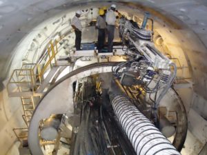
The first of the two machines was launched in March 2008 after an unprecedented onsite assembly. Both of the machines were initially assembled onsite using the Onsite First Time Assembly (OFTA) process. OFTA, rather than assembling the machine in a manufacturing facility, saves both time and money to the contractor in terms of personnel and shipping costs.
Assembly of the first machine took place in a large launch pit at the outlet portal site, using gantry cranes to hoist components into place. Machine parts including the cutterhead, gripper system, forward shield, and telescopic shield were then assembled in a concrete “cradle”. The assembled TBM and back-up then crawled forward by reacting against invert segment pieces installed progressively up to the tunnel entrance. The second Robbins machine was assembled onsite at the opposite end, or the inlet portal.
Geologic conditions consist of quartzite zones up to 450 MPa (65,000 psi) UCS, layered and separated by shale for approximately 50% of the length, with granite (160 to 190 MPa/ 23,000 to 28,000 psi UCS) for the remaining 50%. Both machines feature back-loading 20-inch diameter cutters for longer cutter life in the abrasive conditions. Other design modifications include specially designed drive motors to run each machine at a higher than normal rpm for optimal penetration rates in the hard rock.
TBM Launch
AMR Outlet Tunnel
 Initial conditions at the AMR outlet included intermittent power outages, which were supplemented by onsite generators, as well as difficult geology. Severely blocky ground at the outset tore the conveyor belt and slowed the tunneling process. Large rock blocks made their way through the muck buckets, stopping in transfer hoppers and point loading the conveyor system. To counteract this problem, the spacing of grizzly bars on the muck buckets was reduced and additional bars were added so the boulders could not pass onto the conveyor system. Grill bars were also added to the AMR inlet machine in anticipation of similar ground conditions. In good ground, the grill bars can be removed to allow a higher flow of material into the muck hopper.
AMR Inlet Tunnel
 The Inlet machine was one week away from launch in October 2009 when a 100-year monsoon hit the region. The natural coffer dam wall at the inlet site was not designed to withstand a major flood, and was breached by the flood waters. Flood control doors were not opened in time to release the water downstream, causing the significant rise in water levels. The launch pit was inundated with over 20 m (66 ft) of water, leaving the crown of the TBM beneath over 10 m (33 ft) of water for approximately ten days until it could be pumped out.
The TBM and backup were jacked back 12 m from the tunnel face to allow removal of the cutterhead and inspection of the main bearing. Cleanup lasted approximately 14 days which included jet washing the machine and removing silt 300 to 400 mm (12 to 16 in) thick which was left on the machine. A major portion of the TBM components were replaced to get the machine back to running condition.
Tunnel Excavation
The beginning of 2010 (6th km) was marked by the first cutterhead refurbishment, deemed necessary to restore bucket lip housings and face wear plates that were severely worn out after excavation of unusually abrasive and hard rock. After refurbishment, the monthly advance slowly improved to within the range of 300-330m. However, consistently challenging conditions during the same time period in 2010 meant average machine utilization was 21.7%.
 To help avoid sudden breakdowns or delays caused by the constant extremely high vibrations propagating from the cutterhead up to the back-up bridge gantry, a careful inspection of all the exposed components was implemented during and after each stroke, or at any time that a sudden change in boring values or other anomalies occurred. All the cutter fasteners, bucket lip bolts, grill bars, main bearing studs, seal clamp rings, seals and wear bands suffered from the excessive stresses induced and needed to be checked constantly. With the implementation of this regime it was possible to reduce the number of blocked cutters and any possible damage to the head. A second cutterhead refurbishment was planned and carried out in the 12 weeks between June and September 2011 by replacing and removing all damaged carbide wear plates, in particular in the outer/gage section of the head.
When tunneling with limited geological data in a remote location, it is quite often necessary to find technical and practical countermeasures, particularly in the case of AMR where adverse excavation conditions where a large diameter machine is boring one of the world’s longest tunnels. Constant monitoring of the boring data, and a routine maintenance regime play a significant role in the system performance. While hard rock conditions are continuing to be a challenge for both the inlet and the outlet portal tunnels, training of the crew members as to how to deal with the unusually abrasive and hard rock has been invaluable.
As of November 2020, both machines have excavated at least 70% of their respective tunnels. Since the jobsite has continually experienced very hard, abrasive rock conditions, it has allowed for research and testing of harder, more durable cutter rings because of the extreme conditions.
Pula Subbaiah Veligonda Project
Double Shield bores Water Transfer Tunnel beneath Indian Tiger Sanctuary
Project Overview
 Beneath India’s largest tiger sanctuary, the Nagarjuna Sagar National Park, tunnel boring machines are orchestrating one of the largest water transfer schemes in India. A Robbins Double Shield TBM is boring tunnel No. 2 of the Pula Subbaiah Veligonda project for Coastal Projects Ltd. (CPL), of the CPL/ Hindustan Construction Company (HCC) JV.
On the Krishna River, on the right bank of the Srisailam Canal, lies the future inlet site for the Pula Subbaiah Veligonda Project. Once complete, the system will draw 1.2 billion cubic meters (317.0 billion gallons) of flood water annually from the foreshore of the Srisailam reservoir. Two parallel, 19.2 km (11.9 mi) long tunnels will transfer water via a network of five canals to over 1,600 square kilometers (395,368 acres) of farmland in the three districts of Prakasam, Nellore, and Kadapa. Up to 243 cubic meters per second (64,193 gallons per second) of water will travel through the bored tunnels to a feeder canal.
In October 2007, a USD $180 Million contract was awarded to Coastal Projects Pvt. Ltd (CPPL). In November, CPPL signed a contract for a 10.0 m (32.8 ft) diameter Robbins Double Shield TBM and continuous conveyor system. In addition to the machine and conveyor, spares and key operating personnel were sent to the jobsite to excavate tunnel No. 2 starting from the outlet end.
The Veligonda tunnel No. 2 is located in sedimentary rock on the western margin of the Cuddapah Basin, where a number of faults and folds make for complex geology. Rock includes quartzite with interbedded shale (60%) and shale with limestone and phyllite (40%) ranging from 90 to 225 MPa (13,000 to 33,000 psi) UCS. Two major faults are present along with some ground water.
Equipment Design
The Double Shield machine utilizes sixty-seven 20-inch diameter back-loading cutters to combat the tough ground conditions. Specially designed drive motors allow the machine to run at a higher than normal RPM, compensating for low penetration rates in the hard rock. In squeezing ground, the cutterhead is also capable of vertical movement allowing for overboring. The machine also has a probe drill which allows for verification of geology 30 m (98 ft) ahead of the TBM. The drill is capable of 360º rotation and can alternatively serve as a grout consolidation drill. Large 40 kW (54 hp) dewatering pumps located on the back-up system have been specially designed to pump any water away from the tunnel face. As the TBM bores, it erects 300 mm (12 inch) thick concrete segments in a 6+1 arrangement, making the final tunnel diameter 9.2 m (30 ft).
Muck haulage requires one of the most extensive conveyor systems ever used in India. The continuous steel cable belt, the longest single flight ever provided by Robbins, will eventually extend 19.2 km (11.9 mi) and requires four main drives and three booster drives.
Launch and Assembly
 The machine was assembled in just four months using Onsite First Time Assembly (OFTA). OFTA is a process that allows machine components to be initially assembled at the jobsite, rather than in a manufacturing facility, typically providing savings in terms of man-hours and shipping costs. Assembly went well despite harsh local temperatures, which can climb to 45˚C (113˚F) daily. In addition, some components could only be installed at night due to thermal expansion in the midday heat.
Excavation
 The Robbins TBM was launched into difficult ground at rates of up to 330 m (1,080 ft) per month, by adopting an extensive program of probe drilling and pre-grouting. Multiple drill holes were bored 30 m (100 ft) ahead prior to every machine push, and grout was then injected at depths of 25 to 30 m (80 to 100 ft). The Robbins TBM then advanced into an unforeseen area of disturbed geology and was inundated with flowing material. The machine became stuck, despite the probe drilling program. It was freed by excavation of a bypass tunnel and continues to excavate in difficult geology.
Updates of this project will be posted as boring continues.
KOPS II Hydropower Project
Project Overview
 The KOPS II Hydropower project is located inside the Alps Mountains, drawing from the same reservoir as the KOPS I hydropower station, commissioned in 1969. The stations are supplied by the Rifa balancing reservoir, located between the tourist centers of Gaschurn and Partenen. The KOPS II pump station and headrace tunnel was built to supply power to the grid during peak demand and to ensure long-term network stability. Being that KOPS II uses the same reservoirs, no additional water was needed compared to KOPS I. Also, KOPS II uses an existing high-voltage line currently used by KOPS I.
Construction began at Kops II in 2004/2005, after Swietelsky Tunnelbau GmbH, Torno SA and Torno Int. S.p.A JV signed the contract for a 5.54 m (18.0 ft) Robbins Double Shield TBM. Construction of not only the tunnel, but the entire hydropower plant, was under strict watch as an Environmental Impact Assessment (EIA) was initiated. More than 500 regulations had to be followed assuring that construction would be done in an environmentally friendly way and in a tight time frame of 42 months.
The completed KOPS II plant provides an additional 450 MW in turbine mode and pump mode to the already existing 247 MW hydropower plant.
Geology
Geology on the tunnel alignment consisted of schist gneiss, migmatite gneiss, mica-schist, amphibolite gneiss, hornblende gneiss, granite-gneiss and aplite gneiss ranging from 30 to150 MPa (4,000 to 22,000 psi) UCS.
TBM Design and Tunnel Excavation
 The Robbins TBM used 483 mm (19 in) back-loading cutters to bore through the very challenging and mixed geology. The cutterhead was designed with 9,074 kN (2,040,000 lb) of thrust and 2,159,424 N-m (1,591,300 lb-ft) of torque. The TBM power was 1,575 kW (2,112 hp).
Boring commenced on the headrace tunnel on July 20, 2006. The TBM was one of the first machines to use a back-loading 19 inch cutterhead. The resulting cutter blockage percentage ratio was very low—only 2% over the duration of the project, compared to the more typical rate of 10-15%. The KOPS II pump storage plant went into operation in 2008.
The Abdalajis tunnels
Project Overview
 Spain’s high-speed rail network, known as AVE, involves links between the major cities Cordoba, Madrid, Seville, and Malaga. The twin 7.1 km (4.4 mile) long Abdalajis tunnels are part of this rail network and they will contribute to Spain’s overall goal to keep all major cities within four hours travel time from Madrid.
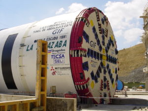
In 2001, the project owner Gestor de Infraestructuras Ferroviarias (GIF) awarded construction contracts separately for each tunnel. The east tunnel was awarded to a Dragados-led consortium called UTE Abdalajis, comprising Dragados, TECSA, SELI, and Jaeger. The west tunnel was awarded to a consortium called UTE Abdalajis Oueste (SACYR S.A., Somague-Engenharia). The two groups shared the main portal site and used nearly identical tunnel boring machines.
Both consortiums chose Double Shield TBMs designed by Robbins for Mitsubishi Heavy Industries. The machines were initially built in Spain by Duro Felguera. They were then assembled onsite with both Robbins and Mitsubishi technicians supervising the assembly.
Geology
The Abdalajis tunnels pass through a variety of rock types, including dolomitic limestone, quartzite, conglomerates, and sandstone. In the deepest part of the tunnels the strata is heavily fractured and karstic conditions in the limestone may harbor considerable amounts of water. The entire span of each tunnel contains more than twenty fractured and faulted areas.
TBMs
The TBMs featured sixty-four 17 inch (432mm) back-loading cutters and could generate a cutterhead thrust of 82,500 kN ( 18,546,734 lb). The Robbins Double Shield design generated a maximum cutterhead torque of 18,700,000 N-m (13,792 lb-ft). Both machines came with probe drills and foam application systems for face conditioning.
Tunnel Excavation
Excavation of the eastern tunnel began in November 2003. The custom design of the TBM allowed it to bore through brittle and heavily fractured rock efficiently. The TBM’s production rates along the first 1,590 m (5,217 ft) were very good with advance rates as high as 34 m (112 ft) per day.
In the middle of the tunnel bore, methane intrusions began to increase. Roughly 800 m (2,625 ft) of fractured clay with methane leaks forced stoppages to ventilate the tunnel. Despite these conditions the TBM kept a constant advance rate and encountered more stable limestone at the end of the tunnel before holing through in January 2006.
The west tunnel machine also began boring in November with similar broken ground and methane gas problems. Similar to the east tunnel TBM, the machine kept constant advance rates despite the unfavorable conditions. The TBM also encountered more stable limestone in the final meters of the tunnel. The west tunnel TBM finished roughly 2.5 months after the hole through in the east tunnel.
The Channel Tunnel
Project Overview
 The Channel Tunnel, one of the world’s most famous tunnels, is a 50 km (31 mi) tunnel under the English Channel linking Great Britain to France. This link consists of three parallel tunnels running for 39 km (24.2 mi) under the sea. Two Main Rail Tunnels, about 30 m (98 ft) apart, carry trains from the north and from the south. In between the two tunnels is the Channel Service Tunnel, which is connected by cross-passages to the main tunnels. This service tunnel allows maintenance workers to access the rail tunnels at regular intervals.
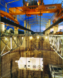
The contractor for the project, Transmanche-Link (TML) chose five Robbins TBMs to participate in boring the crossings. TBMs were deployed at both the U.K. and France Terminals.
Geology
The majority of the Channel Tunnel passes through chalk marl, much of it faulted. Below the Chalk Marl is a thin 2 m (6.5 ft) band of permeable Glauconitic Marl. This rock is a weak sandstone with a stronger rock strength than the Chalk. The bottom of the tunnels pass through stiff clay with some swelling characteristics. The Chalk is much more faulted and prone to water inflows on the French side of the tunnels.
TBMs
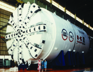 Robbins built five machines for this project, each designed for the geology of a specific length of tunnel.
The high water pressures predicted in the folded and faulted chalk on the French side required the use of three Earth Pressure Balance machines (EPBMs). These machines featured sealed cutter chambers to withstand high water pressures and screw conveyors to carry the cut material from the face.
Robbins built two EPBMs for the French side of each Main Rail Tunnel. These 1,100 tonne (1,200 ton), 8.8 m (29 ft) diameter machines had a cutterhead thrust of 19,613 kN (4,413,000 lb) and generated a maximum torque of 12,748,645 N-m (9,410,000 lb-ft).
The undersea French side of the Channel Service Tunnel also required an EPBM. This machine featured a 5.6 m (18 ft) diameter cutterhead, a cutterhead thrust of 39,227 kN (8,837,000 lb), and a maximum torque of 3,510,781 N-m (2,591,000 lb-ft).
Two Double Shield TBMs were built for the U.K. terminal because fewer water inflows were predicted. Robbins designed these machines to withstand unstable and faulted rock conditions. The 8.36m (27 ft) diameter machines included 13 inch (330 mm) cutters and 65,871 kN (14,821,000 lb) of thrust. The machines generated a maximum 5,727,084 N-m (4,227,660 lb-ft) of torque.
Tunnel Excavation
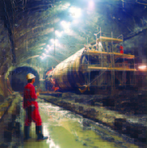 Machines were deployed on both sides of the tunnels in December 1987. The three French seaward TBMs encountered water inflows almost immediately, forcing the use of the sealed mode of operation much earlier than anticipated. The sealed cutterheads of the machines could withstand 10 bar (145 psi) of water pressure; however, additional measures were required to seal the remainder of the machines against water inflow.
The tail shields of the TBMs were fitted with multiple rows of wire brush seals that pressed against the outside diameter of the concrete segment lining. Grease was injected into wire brushes and the 100 mm (4 in) space between the metallic brushes and the tunnel lining. Grout lines were fitted into the tail shield allowing fine cement grout to be injected into the 152 mm (6 in) annulus between the tunnel lining and the ground. This method sealed the tunnel lining as the TBMs advanced. In spite of the difficult conditions, advance rates improved throughout the boring with the Robbins service tunnel machine averaging 714 m (2,342 ft) per month for the project.
The U.K. machines also experienced some difficult tunneling conditions at the outset. Unforeseen water inflows in a 3.2 km (2.0 mi) stretch caused the machines to slow their progress as each section of tunnel had to be grouted in advance of boring. After passing through this section of tunnel, the machines experienced no further difficulties and began averaging 149 m (490 ft) a week. The Robbins machines on the U.K. side averaged 873 m (2,864 ft) per month and set world records for a best day of 75.5 m (247.7 ft), a best week of 428 m (1,404 ft), and a best month of 1,719 m (5,640 ft) — all of which have yet to be beaten.
 Muck transport on both sides of the tunnel was complicated but worked well. In the U.K. a rail system of 500 muck cars transported muck back to the access adit at Lower Shakespeare Cliff and fed it onto a high-speed conveyor. The conveyor then dumped the muck into lagoons behind sea walls in the English Channel. In all, about 4 million m3 (5.23 million cubic yards) of chalk were dumped at the site. The area, called Samphire Hoe, is now a popular park.
On the French side muck was crushed and mixed with water in a chamber at the bottom of the Sangette access shaft. It was then pumped up the shaft and behind a 30.5m (100 ft) dammed reservoir.
 In December 1990, the French and British TBMs met in the middle and completed the Channel Service Tunnel bore. In all of the tunnels the French TBM was dismantled while the U.K. TBM was turned aside and buried.
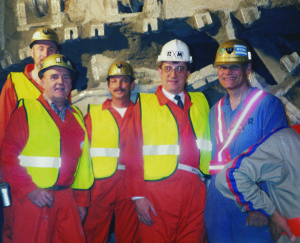
The Main Rail Tunnels met on May 22, 1991 and June 28, 1991. Both accomplishments were celebrated with breakthrough ceremonies to commemorate the building of one of the world’s longest and most ambitious undersea tunnels.
Boston Harbor Project
Project Overview
 The Boston Harbor Project includes one of the largest wastewater treatment plants in the United States. The project required two undersea tunnels to carry wastewater to and from the new treatment plant. One tunnel conveys treated waste water through a 15.2 km (9.4 mi) long effluent outfall tunnel beneath Boston Harbor. The outfall tunnel transports the water from the Deer Island Treatment Plant into Massachusetts Bay. Since the completion of the project in 1998, effluent discharges into Boston Harbor have ceased and concentrations of toxic bacteria, waste solids, and nitrogen have decreased dramatically.
In 1990, The Massachusetts Water Resource Authority awarded the construction contract to Kiewit-Atkinson-Kenny Joint Venture. The contractors selected an 8.1 m (26.5 ft) diameter Robbins Double Shield TBM to bore and install the lining in the effluent outfall tunnel.
Geology
The prominent rock type along the tunnel is Cambridge argillite in beds 1 mm to 8 cm (.04 to 3.15 in) thick with occasional 1.5 m (4.9 ft) formations. Volcanic flows and occasional tuff deposits are also embedded in the argillite. Other geologic features include igneous dikes and sills of diabase with some basalt, andesite, and felsite.
TBM and Back-up
Robbins built the Double Shield TBM to handle the variable geology of the undersea tunnel. While in “double shield mode” the machine simultaneously installed pre-cast concrete lining segments while excavating. This feature gave the machine a faster overall advance rate than with the sequential operation of “single shield mode”.
The machine’s cutterhead drive consisted of eight electric motors generating 2520 kW (3360 hp) and supplying 3665 kN-m (2,700,000 lb-ft) of torque to the cutterhead. The cutterhead thrust was 111,350 kN (2,500,000 lb) and the machine’s 50 – 17 in (432 mm) diameter cutters could be changed from behind or in front of the cutterhead.
The source of cutterhead thrust could also be changed depending on boring conditions. In good conditions (self-supporting ground, usually hard rock), the machine would bore in “double shield mode,” where thrust reacted through a conventional gripper system into the tunnel walls. In soil or fractured zones where the tunnel walls were too weak, the machine would operate in “single shield mode”, where the thrust reacted directly to the tunnel lining segments via a set of auxiliary cylinders in the tail shield.
The TBM towed a back-up train with eight 10.7 m (35 ft) long double-deck gantries, via hydraulic cylinders. The upper decks of the gantries housed the two main 2000 kVA transformers, electrical control cabinets, dust scrubber system and auxiliary equipment. Flexible 1.5 m (4.9 ft) diameter ducting extended from a storage cassette mounted on the last back-up gantry to provide ventilation. A double-track rail system installed on the first six gantries provided storage for rail cars carrying pre-cast segments and pea gravel for temporary segment support, rails and ties.
Tunnel Excavation
 The TBM began excavating from the access shaft in July 1992. Early in the drive, the TBM battled more blocky rock than predicted in the geological reports. Hard rock and water inflows continued to slow progress throughout the drive.
In 1993 and again in 1995 and 1996, hard rock and heavy water inflows required face grouting and slowed TBM progress. Most of the water inflows reached rates of 19,000 to 26,600 liters (5,019 to 7,027 gallons) per minute. Probe drilling and grouting in these sections resulted in slower TBM advance rates.
From March 1996 onward, TBM excavation continued concurrently with hand excavation of the crossover adits. The machine broke through on September 19, 1996 after excavating over 15 km (9.3 mi). The TBM achieved a best day of 44.2 m (145 ft) and a best week of 195.1 m (640 ft).
This TBM’s achievements are remarkable considering the extremely high volume of water inflow and large variations in geology throughout the drive.
Recent Posts
- Cooperative Innovation at the Manhattan Tunnel Project: Digger Shields with Expandable Segments to Excavate Complex Fill
- Robbins celebrates TBM acceptance for Ellicott City North Tunnel
- Huge Robbins Slurry TBM breaks through in Hiroshima
- Robbins TBMs break through at Delhi Metro DC-07 Project
- RETC 2025