 Close
Close  Menu
Menu 
Project Categories: EPB TBM
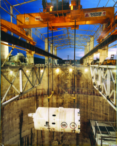
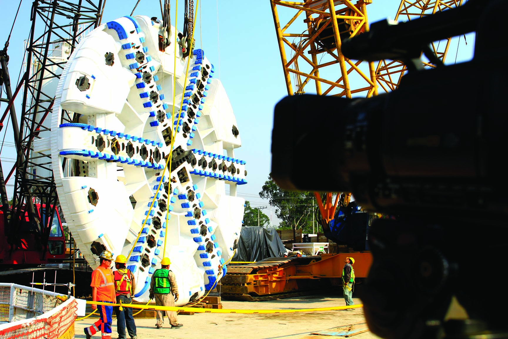
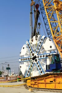
San Francisco Central Subway
Robbins EPBs Bore Twin Tunnels Below Active BART Line
Project Overview
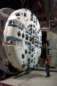
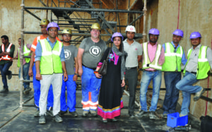
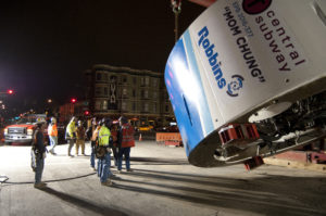 San Francisco’s Central Subway rail tunnels, snaking through downtown areas, were required to be driven below the existing Bay Area Rapid Transit (BART) line. Robbins provided two 6.3 m (20.7 ft) diameter EPBs to bore twin tunnels for the city’s newest rail route. The machines, operated by contractor Barnard/Impregilo/Healy JV, were nicknamed “Mom Chung” and “Big Alma”, after local historical figures.
Geology
Geological testing revealed layers of mixed ground. Two 2.5 km (1.5 mi) long tunnels were excavated through ground ranging from soft soils to thinly bedded siltstone, shale and sandstone bedrock, as well as concrete diaphragm walls. The TBMs were designed with a number of special features to efficiently manage the varied geology, navigate the steep and turning alignment, and bore in what has been rated as “Potentially Gassy with Special Conditions” by Cal/OSHA.
Machine Design and Excavation
 Steering the TBMs accurately through tight curves was one of the key challenges of the project. A mixed face cutterhead was selected and designed to excavate the anticipated wide variety of ground, while active articulation was integrated between the TBM shields to lessen the risks of segment damage, ring deformation, and settlement during boring through curves. Both machines were designed to enable smooth excavation around tight turns with active articulation to excavate curves as small as 137 m (450 ft) in radius. Robbins continuous conveyors offered efficient muck removal throughout tunneling.
Low cover, nearby utilities, and sensitive structures required analyses and design precautions in order to limit settlement impact. This was especially true of a crossing directly below live rail tunnels for the Bay Area Rapid Transit (BART). Compensation grout pipes were put into place as a contingency, but were not needed as the machines passed just 3.4 m (11 ft) below the rail lines with minimal settlement. Careful monitoring of the key TBM parameters ensured that boring did not impact the critical structures over the tunnel that ran through the heart of downtown San Francisco.
Breakthrough
 The first of the two machines holed through on June 2, 2014, the second followed close behind and broke through on June 11, marking the completion of the twin tunnels. Both Robbins machines achieved swift advance rates of up to 40 m (131 ft) in 24 hours and 513 m (1,683 ft) in one month.
Jaipur Metro
Twin EPBs Excavate Under Historic Structure
Project Overview
 The city of Jaipur, India is encircled by a wall six meters high and three meters thick, with seven gated openings. It is below these delicate and iconic structures that Jaipur’s first Metro, Line 1, travels. For this project, Contractor Continental Engineering Corporation (CEC) decided to refurbish their two 6.52 m (21.3 ft) diameter Robbins EPBs. The machines bored twin tunnels 2.3 km (1.4 mi) in length, directly beneath the historic Chandpole Gate.
Geology
In this particular project, the geology was not anticipated as a main concern. The bores consist mainly of silty sands, with a minor amount of clay and gravels. However, the geological conditions coupled with the extremely low overburden in the area of the launch shaft, especially the section passing beneath Chandpole gate, was cause for major concern.
The Machines
The contractor opted to refurbish its two 6.52 m (21.3 ft) diameter Robbins EPBs originally used for the New Delhi Metro Project. The Robbins EPBs were refurbished in India, and customized for the Jaipur project. The original machines for New Delhi bored a straight tunnel and did not require active articulation, but a 430 m (1,410 ft) radius curve in Jaipur necessitated that the machines be articulated. The shields were essentially cut in half and another section put in to form articulation joints in the contractor’s casting yard. In addition, new a+b grouting systems were installed as well as sophisticated tunnel guidance systems to monitor each machine’s position.
Boring Below the Historic Chandpole Gate
Chandpole gate, one of the seven, is directly above the bore path for the Line 1 extension, and serves as a historical landmark. The construction materials of the walls and gate consist of irregularly-sized pieces of stone cemented together with lime mortar and faced with a sand and lime mortar render that provide little to no resistance to tunneling-induced settlement. Contractually the allowable limit for surface settlement was set at 4 mm (.16 in). Yet, there was also an Indian archeological law in place that made the stakes a bit higher. It states, “Whoever destroys, injures, mutilates, defaces, alters, removes, disperses, misuses, imperils or allows to fall into decay a protected monument, or removes from a protected monument any sculpture, carving image, bas-relief, inscription or other like object, shall be punishable with imprisonment for a term which may extend to six months with a fine which may extend to five thousand rupees or with both.”
 The key to boring beneath the gate without any adverse effects relied on refining the TBM operating parameters before the TBM reached the zone of influence. As this had been achieved, these parameters were maintained after the restart and similar results were achieved up until ring No. 75, where surface heave increased slightly. Due to the increase in heave the EPB pressure was reduced to 1.2 bar and cutterhead speed to 1.1 RPM. These changes reduced the heave to within tolerance. Although vibrations levels were minimal, as the TBM approached the gate the cutterhead speed was further reduced to 1.0 RPM to reduce the risk of damage by vibration. The machine passed beneath the gate and through the zone of influence without incident using these parameters. The maximum recorded settlement in the vicinity of the gate was 2 mm (.08 in) and absolutely no adverse effects were sustained to the gate. The lessons learned on the first drive were applied to the second drive and TBM II also passed beneath the gate with minimal settlement and no damage to the gate.
Upper NW Interceptor Sewer
Project Overview
 The Upper Northwest Interceptor (UNWI) sewer system in Sacramento, CA is comprised of nearly 30 km (18 mi) of tunnel. The system was created to ensure both present and future sewer needs are met, particularly during severe wet weather storms when existing systems are at risk of overflowing. The UNWI system was split up into nine sections with Section 1 starting in Natomas and Section 9 ending in Citrus Heights neighborhoods. Sections 3 through 9 were completed by 2008. The system is capable of conveying up to 560 million liters (148 million gallons) of wastewater per day.
On August 22nd, 2007, Sacramento Regional County Sanitation District (SRCSD) awarded the USD $97.3 million construction contract to Traylor/Shea JV to complete Sections 1 & 2 of the UNWI Sewer Project. Traylor/Shea chose a 4.25 m (13.9 ft) Robbins EPB optimally designed for ground consisting of clay and running sand.
EPBM
The Robbins EPBM was equipped with a spoke-type cutterhead and wear resistant cutterhead plates. Bentonite foam injection ports in the cutterhead allowed for stabilization of the tunnel face and smooth muck flow. Muck was removed using a 500 mm (20 in) diameter shaft-type screw conveyor emptying onto a Robbins continuous conveyor system. Two-component backfill grout was used to further stabilize ground behind segments, helping to reduce the risk of surface subsidence. The advantage of using a two-component grout was that the mixture could be pumped using a standard concrete pump, rather than the high-pressure pumps often needed with one-liquid concrete fills. By reducing the pump pressure, there was less chance of disturbing the surrounding soils.
The machine, which used active articulation rather than passive articulation, was able to negotiate curves down to a 400 m (1,300 ft) radius. Active articulation was chosen because it allows the front and rear shield to turn independently of the thrust cylinders, eliminating the common problem of ring deformation in curves.
Tunnel Excavation
 The EPB began boring in January 2009 from the New Natomas Pump Station. The tunnel profile below the spring line consisted mostly of sand, while the top part of the tunnel face was primarily in clay. The tunnel invert ranged from 7 to 14 m (23 to 46 ft) below the surface, with groundwater present throughout.
To shorten construction time, Traylor/Shea and the SRCSD wanted to use a new type of tunnel liner, one never before used in the United States. Precast concrete segments 228 mm (9 in) thick were molded with embedded PVC sheets 1.8 mm (0.07 in) thick. The PVC liner protects the concrete from degradation due to corrosive sewer gases. The final result is a finished tunnel that requires no final carrier pipe, reducing time for the pipeline to become functional.
Continuous conveyors were also chosen by Traylor/Shea due to the increased efficiency, reduced startup time, and higher availability than muck cars in most situations. The conveyor system was specially designed for the 5.7 km (3.6 mi) tunnel in varying ground conditions. Features included sealed transfer points and receiving hoppers, with urethane rubber being used to seal points and minimize spillage. The foam and bentonite additives helped maintain a smooth consistency of muck which flowed on the conveyor even when significant ground water was present.
Throughout the bore, the machine achieved some of the highest rates in soft ground TBM tunneling with multiple advances of 210 m (690 ft) per week, as well as daily rates of 50 m (165 ft) in three eight-hour shifts. In addition, the continuous conveyor system operated at over 90% availability for the duration of tunneling. Boring was completed on Nov. 21, 2009, when the Robbins EPBM broke through more than two months ahead of schedule.
Guangzhou Metro, GuangFo Line
Project Overview
 Since 2006, China has invested nearly USD $200 billion in rail infrastructure – a plan that promises to be one of the largest national railway expansions since that undertaken by the U.S. in the 19th century. Guangzhou’s metro expansion is part of the Pearl River Delta Inter-City Rapid Rail Project and China’s first ever inter-city rail link. The 32.2 km (20 mi) Guang-Fo line running between Guangzhou and Foshan was awarded in 12 separate lots. The owner, Guangzhou Metro Company, chose to utilize 16 different TBMs.
Lot 12, running between Jushu, Xilang, and Hedong stations, was awarded in 2007 to the China Communication Construction Corp., 2nd Navigation Engineering Bureau Ltd. (CCCC). The contractor, CCCC, selected two 6.3m (20.5 ft) diameter Robbins EPBMs for the parallel 2.6 km (1.6 mi) long rail tunnels. The two cutterheads began turning in January and February 2009, after being launched from the cut and cover site of Jushu station in southern Guangzhou.
Geology
The geology on the metro’s Lot 12 consisted of a complex layered profile, ranging from highly weathered to slightly weathered granite, coarse sand, and silt at pressures up to 4 bar. Around 70% of the tunneling was through a mixed face, with the alignment above the spring line in soft soils and the bottom half of the tunnel in rock of at least 50 MPa (7,250 psi) UCS. The remaining 30% consisted of flowing sand with high water content.
EPBM
Both Robbins EPBMs were designed with spoke-type cutterheads including large opening ratios of 37%, which allowed for smooth flow of muck into the mixing chamber. Both 432 mm (17 in) hard rock single disc cutters and carbide bits were used to combat the mixed ground conditions expected.
Four independent foam injection points on the cutterhead were used to further consolidate the muck flow. Foam was used on the Guangzhou tunnels because it was less costly and it also reduced the required cutterhead torque. Muck was removed using an 800 mm (31.5 inches) diameter shaft-type screw conveyor due to the fact that no large boulders were predicted. Active articulation was chosen for this project, mainly because much of the transit twists beneath the city, with curve radii as small as 200 m (656 ft).
Tunnel Excavation
 The two Robbins EPBs were launched in December 2008 and January 2009 respectively. After only seven months of boring, the two machines achieved more than 16 project records including a best month of 377 m (1,235 ft) – higher than any of the 16 TBMs that have worked on the Guang-Fo Metro Project.
Surface settlement was a major concern as the tunnels run beneath rivers, research sites, roadways, and vulnerable building foundations. Back-fill grout was used to fill the gap between the 300 mm (12 in) thick, pre-cast concrete segment rings and the surrounding soil. Some of the high-risk areas included the 80 m (262 ft) wide, 4 m (13 ft) deep Huadi River between Jushu and Xilang stations, and also the Pearl River Fisheries Research Institute, which has numerous sensitive ponds used for research into high-yield fish farming.
Both machines finished a month ahead of schedule, and operated around 95% availability. As of August 2009, only 66 disc cutters had been changed on the first machine and 46 on the second, while no carbide bits had been changed on either of the TBMs. The first machine completed its initial breakthrough into the Xilang station on August 15, 2009 and its final breakthrough in September. The second machine broke through into the Xilang station in September and made its final breakthrough in October 2009.
New Delhi Metro Extension Project
Project Overview
 Phase II of the New Delhi Metro Extension Project is an ambitious plan to add 53 km (33 mi) of new rail lines to cut transportation times, in particular for when the city hosted the Commonwealth Games in 2010. Owners Delhi Metro Rail Corporation (DMRC) completed Phase I of the project in November 2006, adding 65 km (40 mi) of track and 59 stations. Phase II, at a cost of USD $1.8 billion, involved multiple soft ground tunnels to be bored by Earth Pressure Balance Machines (EPBMs) between underground stations excavated by cut and cover.
On February 1, 2007, Robbins and Mitsubishi Heavy Industries (MHI) signed a contract with the CEC/Soma JV for two 6.5 m (21.4 ft) diameter EPBMs, back-up systems, and cutting tools. The machines were manufactured by Robbins using components from the U.S., India, and China.
On May 15 2008, the first of the two TBMs was launched from an 18 m (60 ft) deep shaft at the Jor Bagh station site. The machines bored parallel 2.0 km (1.2 mi) tunnels connecting the Udyog Bhawan and Green Park areas in New Delhi, as part of the BC-16 contract. The second machine was launched from the same site during the last week of June 2008.
Geology
The tunnels ranged from 8.6 – 14.0 m (28 – 46 ft) below the water table in sandy silt, silty sand and gravels.
Machine Design
Both EPB cutterheads featured a 55% opening ratio to allow a smooth flow of muck and to avoid clogging the cutterhead. The machines used several types of tungsten carbide bits for boring in soft but abrasive ground and shaft-type screw conveyors to remove water-bearing muck. Continuously erected lining along the length of the tunnel consisted of reinforced concrete segments 275 mm (11 in) thick.
Tunnel Excavation
 On September 29, 2008 the first of the two Robbins EPBMs completed its initial bore of 1.0 km (0.6 mi), holing through into the cut and cover Race Course station site. High advance rates of 19 rings installed per day, together with over 90% average availability, contributed to the fast completion. The machine was then dismantled in a reception pit and transported by road to the other end of the 318 m (1,000 ft) long Race Course site, where it began the second half of its bore to the contract boundary at Udyog Bhawan station. During excavation, the machine achieved a project record of 168 rings, or 202 m (663 ft) in one week—faster than any of the 14 other TBMs working on the project.
By April 2009, all four drives initially planned using Robbins machines were complete. Due to scheduling constraints, Continental Engineering Corporation (CEC) opted to use one of the Robbins machines for a fifth, approximately 567 m (1,860 ft) long drive from AIIMS to Green Park station sites. The fifth and last drive broke through on July 14, 2009.
Mexico City Metro Line 12
Project Overview
 The Mexico City Metro is one of the world’s largest, with over 200 km (125 mi) of rail and nearly 4 million daily passengers. The 25.4 km (15.8 mi) long route passes through 22 new stations between Tlahuac and Mixcoac neighborhoods. The 7.7 km (4.8 mi) long tunnel represents the capital’s first new route in ten years, and will service thousands of passengers daily.
In 2007, the Mexican Federal District announced plans to build Line 12 of the Mexico City Metro. The ICA consortium signed a contract for a 10.2 m (33.5 ft) diameter Robbins EPBM, its back up system, and cutting tools. The TBM was the largest to ever bore in Mexico and was the first EPB TBM to be assembled at the jobsite using Onsite First Time Assembly (OFTA).
Geology
Geology on the metro line consisted of layers of clay, sand, and boulders up to 800 mm (30 in) in diameter, as the area is part of a drained lake bed. Ground conditions in Mexico City are very unique and thus required extensive vibration monitoring throughout the bore.
TBM
The giant machine utilized a specially designed two-stage, 1,200 mm (4 ft) diameter ribbon type screw conveyor followed by a shaft-type screw conveyor in order to handle the large boulders. For parts of the tunnel where the ground consisted of very soft clays with high water content, muck was removed using a sludge pump rather than conveyors or muck cars. The machine also featured active articulation, used to prevent segment ring deformation on curves as small as 250 m (820 ft). The spoke-type cutterhead used tungsten carbide knife-edge bits to excavate the soft ground. Additives, as well as two-liquid back-filling, helped control ground subsidence. The two-liquid back-filling system consisted of cement and accelerant, which hardens rapidly and eliminates the need for high-pressure concrete pumps that can disturb the ground. As the machine advanced, it lined the tunnel with 40 cm thick universal concrete segments in a 7+1 arrangement.
The Robbins EPB was launched on February 15, 2010, after just eight weeks of assembly. The launch shaft, approximately 34 m long by 14 m wide by 17 m deep (112 x 46 x 56 ft), was located in one of the most densely urban areas of the city. Due to the small launch pit, the machine bored the first 70 m (230 ft) of tunnel using umbilical cables connected to back-up gantries on the surface. Gantries were then lowered into the shaft successively as the machine bored forward.
Tunnel Excavation
Much of the tunnel was under very low  cover of 7.5 m (25 ft), which required careful monitoring of surface subsidence. The project’s location at the city center was in close proximity to a number of structures. The tunnel route took the machine within 1.5 m (4.9 ft) of a 4 m (13 ft) diameter collector sewer, within 2.0 m (6.6 ft) of building foundations, and just 3.5 m (11.5 ft) below the metro’s active Lines 2 and 3.
Breakthrough
The machine reached the its first station during the last week of April 2010 after boring a total of 495 m (1,624 ft). There were several difficulties with the sludge line, but after engineers redesigned the system it worked exceptionally well. From there, the EPB continued on to six more stations, undergoing routine maintenance at each one. On March 1, 2012, the machine completed its successful tunneling run.
Line 12 of the Mexico City Metro is the longest in the system. The new line carries an average of 367,000 passengers each day, making it the fourth busiest commuter rail route in the capital.
The Channel Tunnel
Project Overview
 The Channel Tunnel, one of the world’s most famous tunnels, is a 50 km (31 mi) tunnel under the English Channel linking Great Britain to France. This link consists of three parallel tunnels running for 39 km (24.2 mi) under the sea. Two Main Rail Tunnels, about 30 m (98 ft) apart, carry trains from the north and from the south. In between the two tunnels is the Channel Service Tunnel, which is connected by cross-passages to the main tunnels. This service tunnel allows maintenance workers to access the rail tunnels at regular intervals.
The contractor for the project, Transmanche-Link (TML) chose five Robbins TBMs to participate in boring the crossings. TBMs were deployed at both the U.K. and France Terminals.
Geology
The majority of the Channel Tunnel passes through chalk marl, much of it faulted. Below the Chalk Marl is a thin 2 m (6.5 ft) band of permeable Glauconitic Marl. This rock is a weak sandstone with a stronger rock strength than the Chalk. The bottom of the tunnels pass through stiff clay with some swelling characteristics. The Chalk is much more faulted and prone to water inflows on the French side of the tunnels.
TBMs
 Robbins built five machines for this project, each designed for the geology of a specific length of tunnel.
The high water pressures predicted in the folded and faulted chalk on the French side required the use of three Earth Pressure Balance machines (EPBMs). These machines featured sealed cutter chambers to withstand high water pressures and screw conveyors to carry the cut material from the face.
Robbins built two EPBMs for the French side of each Main Rail Tunnel. These 1,100 tonne (1,200 ton), 8.8 m (29 ft) diameter machines had a cutterhead thrust of 19,613 kN (4,413,000 lb) and generated a maximum torque of 12,748,645 N-m (9,410,000 lb-ft).
The undersea French side of the Channel Service Tunnel also required an EPBM. This machine featured a 5.6 m (18 ft) diameter cutterhead, a cutterhead thrust of 39,227 kN (8,837,000 lb), and a maximum torque of 3,510,781 N-m (2,591,000 lb-ft).
Two Double Shield TBMs were built for the U.K. terminal because fewer water inflows were predicted. Robbins designed these machines to withstand unstable and faulted rock conditions. The 8.36m (27 ft) diameter machines included 13 inch (330 mm) cutters and 65,871 kN (14,821,000 lb) of thrust. The machines generated a maximum 5,727,084 N-m (4,227,660 lb-ft) of torque.
Tunnel Excavation
 Machines were deployed on both sides of the tunnels in December 1987. The three French seaward TBMs encountered water inflows almost immediately, forcing the use of the sealed mode of operation much earlier than anticipated. The sealed cutterheads of the machines could withstand 10 bar (145 psi) of water pressure; however, additional measures were required to seal the remainder of the machines against water inflow.
The tail shields of the TBMs were fitted with multiple rows of wire brush seals that pressed against the outside diameter of the concrete segment lining. Grease was injected into wire brushes and the 100 mm (4 in) space between the metallic brushes and the tunnel lining. Grout lines were fitted into the tail shield allowing fine cement grout to be injected into the 152 mm (6 in) annulus between the tunnel lining and the ground. This method sealed the tunnel lining as the TBMs advanced. In spite of the difficult conditions, advance rates improved throughout the boring with the Robbins service tunnel machine averaging 714 m (2,342 ft) per month for the project.
The U.K. machines also experienced some difficult tunneling conditions at the outset. Unforeseen water inflows in a 3.2 km (2.0 mi) stretch caused the machines to slow their progress as each section of tunnel had to be grouted in advance of boring. After passing through this section of tunnel, the machines experienced no further difficulties and began averaging 149 m (490 ft) a week. The Robbins machines on the U.K. side averaged 873 m (2,864 ft) per month and set world records for a best day of 75.5 m (247.7 ft), a best week of 428 m (1,404 ft), and a best month of 1,719 m (5,640 ft) — all of which have yet to be beaten.
 Muck transport on both sides of the tunnel was complicated but worked well. In the U.K. a rail system of 500 muck cars transported muck back to the access adit at Lower Shakespeare Cliff and fed it onto a high-speed conveyor. The conveyor then dumped the muck into lagoons behind sea walls in the English Channel. In all, about 4 million m3 (5.23 million cubic yards) of chalk were dumped at the site. The area, called Samphire Hoe, is now a popular park.
On the French side muck was crushed and mixed with water in a chamber at the bottom of the Sangette access shaft. It was then pumped up the shaft and behind a 30.5m (100 ft) dammed reservoir.
 In December 1990, the French and British TBMs met in the middle and completed the Channel Service Tunnel bore. In all of the tunnels the French TBM was dismantled while the U.K. TBM was turned aside and buried.
The Main Rail Tunnels met on May 22, 1991 and June 28, 1991. Both accomplishments were celebrated with breakthrough ceremonies to commemorate the building of one of the world’s longest and most ambitious undersea tunnels.
Tampa Bay
Project Overview
 The South Central Hillsborough Intertie tunnel passes under the Alafia River in Tampa Bay. The tunnel is part of Master Water Plan Stage B, an ambitious three-stage plan to replenish Florida’s depleted groundwater.
Tampa Bay Water, the project owner, awarded Contract 2 for the South Central Intertie to Kenko Inc. in 2002. The contractor chose an innovative new solution to deal with the difficult ground conditions of the tunnel: a Robbins hybrid EPB shield machine.
Geology
The tunnel travels though the extremely permeable, highly fractured limestone of the Floridian aquifer with over 2.5 bar of hydraulic face pressure. Above the limestone is a layer of very stiff green clay and above the clay is a 4.6 m (15 ft) thick layer of loose, silty fine sand.
EPBM
The contractor chose Robbins because they needed design parameters that encompassed hard rock TBMs, EPBMs, and slurry shields. The EPBM featured eight double and four single backloading 17 inch (432 mm) cutters. The machine was capable of 5,783 kN (1,300,000 lb) of thrust and could generate a torque of 409,457 N-m (302,000 lb-ft) at the cutterhead.
Two face ports at each side of the machine permitted drilling and grouting in difficult conditions. Excavated ground was extracted with a 17 inch (432 mm) diameter invert auger screw. The muck was then conveyed to a mixing chamber to agitate and crush the limestone. The entire excavation system was a closed and pressurized face built to withstand up to 3 bar of hydraulic pressure.
From the mixing chamber, the muck traveled to a slurry pump installed inside the tunnel. The slurry pump transported the muck in a tube to the shaft where it connected with a second pump that brought the muck to the top of the shaft. The slurry pumps directly discharged the cuttings to the surface because the limestone was too porous to form a matrix. Therefore, the sluggish characteristics of the muck made muck transport via screw auger into muck cars too difficult.
Tunnel Excavation
 The hybrid EPBM began boring on May 27, 2002. In the early stages of tunnel excavation, the machine operated in usual EPB mode and material was removed with muck cars.
As the machine continued boring, it encountered increasing hydraulic loads of up to 2.5 bar. This anticipated condition was treated with a circular break system that kept the EPBM in place.
However, the high water pressures prevented the excavated material from forming a plug in the screw conveyor. Injection of ground conditioning additives did not improve the situation and water inflow to the tunnel continued. The mucking system was then converted from muck cars to the more efficient slurry system involving slurry pumps.
After the conversion, the EPBM progressed well and broke through on August 22, 2002 only 3 mm (1/8 in) off of target.
Chengdu Metro Line 2 Lot 18
Robbins EPB sets Record Rates in Chengdu
Project Overview
 Chengdu’s Metro Line 2 includes 26 stations and 17.6 km (10.9 mi) of tunnels between Longquandong and Shiniu areas of the city. Seven lines totaling 274 km (170 mi) are planned to be operational by 2035, and will service 13.1 million daily passengers.
The contractor, CRCC Bureau 23, selected a Robbins EPB with a mixed ground cutterhead for the potentially variable conditions, as well as the back-up system, soft ground cutting tools and spares. The machine was launched in January 2010 to bore two 1.4 km (0.9 mi) sections of parallel tunnel, with a breakthrough at the midway point into an intermediate station. The tunnel alignment allowed the machine to pass 25 m (82 ft) below residential buildings, and included several curves with a minimum 400 m (1,300 ft) radius.
Geology
The tunnels for Lot 18 of Line 2 are located in highly variable, permeable alluvium, stiff sand, and clay, requiring a unique EPB TBM design and careful monitoring for settlement. This complex alluvial geology is unlike that found anywhere else in China. Cobbles averaging from 20 to 80 mm (0.8 to 3.1 in) in diameter were predicted, with diameters of as much as 120 mm (4.7 in) possible.
Machine Design
The mixed ground, spoke type cutterhead was mounted with Tungsten carbide knife-edge bits and seven 17-inch (432 mm) diameter disc cutters around the gauge. A foam injection system was used to stabilize the running ground, allowing each cubic meter of foam mixture to stabilize about 40 rings of ground. Subsidence was intensively monitored and crews were trained to utilize probe drilling and ground consolidation if settlement was detected. Variable frequency (VFD) drives allowed the cutterhead rotation to be kept low (around 1.5 RPM at maximum) to also minimize surface settlement. High advance rates were instead achieved using increased cutterhead torque, which results in a faster rate of penetration. One-liquid type back-filling grout was used to fill the gap between segment lining which consisted of 300 mm (12 in) thick reinforced concrete segments set in a 5+1 arrangement.
Tunnel Excavation
 In June 2010, the machine had broken through into the intermediate station, approximately 1,397 m (4,583 ft) into the 2.7 km (1.6 mi) long tunnel. Following scheduled maintenance, the machine was relaunched to bore the remaining section of the tunnel. Cutter wear was very minimal, with only three cutters changed since the start of boring.
By the time of tunnel completion in December 2010, the machine had achieved a project landmark of 129 m (423 ft) in one week, and 459.5 m (1,507 ft) in one month – higher rates than at least 4 other machines working on Line 2 in similar geology.
Emisor Oriente
Three Robbins EPBs bore Vital Wastewater Tunnel in Mexico
Project Overview
 In an urgent effort to prevent flooding in the urban capital of Mexico City, the National Water Commission (CONAGUA) has ordered the construction of a 62 km (39 mi) long wastewater line, Emisor Oriente, which is expected to help increase Mexico City’s wastewater capacity and ease some of the city’s related problems. Torrential rains and continuing floods in Mexico’s capital during the rainy season have increased the urgency of the job, quickly making it the country’s most critical infrastructure project.
The Emisor Oriente project was divided into six lots – Lots 1, 2 and 5 awarded to Mexican contractor Ingenieros Civiles Asociados (ICA), S.A. de C.V., Lots 3 and 4 to Carso Infraestructura y Construcción, S.A. de C.V., and Lot 6 to Lombardo Construcciones and Constructora Estrella. Three 8.93 m (29.3 ft) Robbins Earth Pressure Balance Machines (EPBs) are excavating Lots 1, 3, 4, and 5 of the tunnel.
Geology
Mexico City is located in the Valley of Mexico. The area contains an ancient, drained lake bed and is surrounded by volcanic mountain ranges. The soil is mainly made up of watery clays running up to 80 m (263 ft) deep with the water table just 2 to 3 m (6.6 to 9.8 ft) below the surface. The ground also contains boulders up to 600 mm (24 in) in diameter. Due to the complex ground conditions, engineers believed for years that the ground would be too difficult to excavate. Despite the challenging terrain, Mexico City’s main wastewater line, Emisor Central, was hand-mined in 1964 approximately 100 m (328 ft) below ground, paving the path for future underground construction projects.
Equipment Features
The Robbins EPBs were designed for the particularly difficult ground conditions they would be facing on the job site. Although difficult ground was anticipated, shaft excavations in 2009 and 2010 revealed much more complex terrain than originally expected, resulting in various modifications on each machine. The EPBs were built with mixed-ground, back-loading cutterheads with carbide cutter bits to deal with variable ground conditions, and ribbon-type screw conveyors to remove large boulders. Redesigned pressure bulkheads were added to the machines to accommodate the higher water pressures of the region, and enhanced wear detection was added to the cutter bits to ensure optimal performance. Robbins continuous conveyors are being used behind each machine in order to quickly remove muck from the jobsite and minimize downtime. Each continuous conveyor system and vertical belt is installed once the machines have bored ahead 150 m (492 ft) from their launch points.
Excavation
One Robbins EPB was launched for Lot 1 on July 13, 2011 – a change from its originally scheduled tunnel drive at Lot 5. A flood at Lot 1 delayed the Herrenknecht machine that was originally designated to bore the area for six months, prompting the contractor to begin boring with the Robbins EPB. The machine started excavation at shaft 5 of Lot 1 using umbilical cables connected to the surface and a sludge pump for muck removal.
Excavation at Lot 1 was fast-tracked because of problems with Mexico City’s main open sewer line, the Gran Canal. The canal was constructed in 1910 and floods its banks on a regular basis, causing road closures and significant health problems to the city’s residents. The canal has a positive vertical alignment, resulting in potentially large volumes of water that could overload current pumping stations and send untreated water back into the city. The canal’s slope loss is due to the area’s sinking lake clays. To help remedy this problem, a treatment plant and pumping station are being constructed in shaft 5 of Lot 1 so water diverted from the section of the Gran Canal to Emisor Oriente can be pumped back into the Gran Canal where the slope has not been compromised. Although there were many challenges the first EPB machine had faced, it was able to make a successful breakthrough 15 months later. Once the Robbins EPB had bored its 4.6 km (2.9 mi) drive to shaft 3A of Lot 1, it was dismantled, removed, reassembled at Lot 5, and began boring its original 8.6 km (5.3 mi) long bore in early 2014.
 The remaining two Robbins EPBs started excavation in 2012, working on 9.2 km (5.7 mi) and 10.2 km (6.3 mi) drives at Lots 3 and 4, respectively. Once excavation was initiated, the machines quickly encountered sections of abrasive basalt rock and ash, boulders and blocky ground that wore on cutting tools and the cutterhead. As a result, the harsh ground conditions led to accelerated wear and damage on some of the cutting tools as well as the screw conveyors.
In efforts to manage the sudden impact of the challenges faced and to maintain control of the situation, the operational parameters at Lots 3 and 4 became a high priority. Improvements to the cutter change time on the central disc cutters were made possible with the design of a new rotary union. To reduce the abrasive wear on the cutterhead, more durable face and gauge scrapers were added to the cutterhead.
The Lot 3 machine underwent additional changes after boring 2.7km (1.6 mi) of its tunnel. The machine was given a new cutterhead fitted with chromium carbide wear plates and smaller openings to reduce blockages. The machine also get a new screw conveyor design with special wear plates, and a reinforced casing with additional gates and injection ports.
At Lot 4, the other Robbins Machine has fared better in soft rock, despite having a lot of water pressure to deal with—the machine even holds the shift record for the project, of 28 rings.
 The Lot 5 Robbins machine, which came from Lot 1, needed major modifications before starting at Lot 5 to help deal with expected water pressures up to 7 bar. The TBM—launched from the deepest shaft at a civil works project in Mexico (150 m)—was fitted with new hyperbaric chambers, as well as a new gantry for the compressors and air tanks. To speed up disc changes at the center of the cutterhead, the rotary union was also modified.
Project Completion
On May 23, 2019, the last of the six 8.93 m EPBs completed tunneling at Lot 4 of Emisor Oriente, thus ending a ten year campaign of nearly 63 km of tunneling in some of the most arduous conditions crews have ever come across.
With the tunneling complete, the secondary lining operation also had to take place from the various headings using telescopic forms. The tunnel was opened for use in December 2019.
Recent Posts
- Twin Robbins EPBs make milestones near Taj Mahal
- Long Haul TBM: Use of a Rebuilt Main Beam Machine at the DigIndy Tunnel System in Indianapolis, IN
- Evaluating TBM Design and Performance, 30 Years Apart: The Lesotho Highlands Water Tunnel, Phase 1 and Phase 2
- Overcoming Mountainous Geology at Nepal's Sunkoshi Marin Project
- Swift Robbins TBM breaks through 11 Months Early