 Close
Close  Menu
Menu 
Project Categories: Single Shield TBM
Delaware Aqueduct Repair
Single Shield TBM will bore through Difficult Conditions to fix the World’s Longest Continuous Tunnel
Project Overview
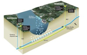 At 137 km (85 mi) long, the Delaware Aqueduct is cited in the Guinness Book of World Records as the world’s longest continuous tunnel. On any given day, it supplies 50-60% of New York City’s drinking water—a metropolis of 8.5 million people—in addition to a further 1 million that live north of the city. It is the largest such water supply tunnel in the United States. In the 1990’s, the New York City Department of Environmental Protection (NYCDEP) discovered that a section of the aqueduct below the Hudson River was leaking 75 million liters of water per day.
The NYCDEP took the decision to repair the tunnel in the largest such project to take place in the 175-year history of New York’s water supply system. A key component of the plan is a bypass tunnel that will connect up with structurally sound portions of the aqueduct and run deep below the Hudson for 3.8 km (2.5 mi). Notably, the tunnel will be bored while the aqueduct is still in service—only after excavation of the bypass will the flow be switched off to allow for the new tunnel to be connected to the existing tunnel. That shutdown is expected to last for five to eight months.
Geology
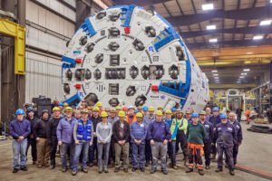
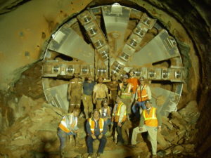
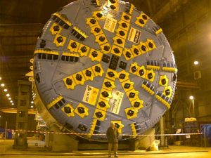
At 183 m (600 ft) below the riverbed of the Hudson, the bypass tunnel in faulted, crumbly limestone will be subject to water inflows at high pressures of up to 20 bar. A specialized 6.8 m (22.3 ft) diameter Single Shield TBM, manufactured by Robbins for JV contractor Kiewit-Shea Constructors (KSC), will bore the tunnel using components aimed at enabling efficient excavation in the difficult geological conditions.
Machine Design
 The machine was designed with Difficult Ground Solutions (DGS) features for the unique conditions.
Water Inflow Control Features
Due to the 20 bar static water pressure expected on the project, a new main bearing sealing system was engineered for the project and is comprised of multiple rows of traditional lip type seals and emergency inflatable seals. In the event of a sudden inrush of high-pressure water, the TBM was designed to be quickly sealed. Knife gates over the muck chute are closed, followed by retraction of the conveyor frame and the belting from the cutting chamber. The bulkhead sealing plate is retracted and finally the stabilizer doors are closed.
Drilling & Grouting Systems
he machine is equipped with two drills in the shields for drilling through the head in 16 different positions and a third drill on the erector to drill through the shields in an additional 14 positions. Drilling and pre-excavation grouting will be a routine job to control and minimize water inflows. In addition, water-powered, high pressure down-the-hole-hammers will allow for drilling 60 to 100 m ahead of the machine at pressures up to 20 bar if necessary.
Pressure-Compensating Disc Cutters
The NYCDEP required that the TBM be capable of withstanding 30 bar of hydrostatic pressure. As such, the use of pressure compensated disc cutters became a necessity. Their unique design incorporates a pressure equalization system to keep water out and protect their bearings when the pressure is high.
Site Preparations
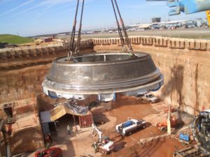
 Two massive shafts were constructed—launch shaft 5B in Newburgh, New York, and a retrieval shaft in Wappinger on the other side of the Hudson. The shafts were constructed by drill and blast with concrete lining installed every 30 m (100 ft). Their construction was completed in March 2016, resulting in a 270 m (885 ft) deep, 9 m (30 ft) diameter shaft at Newburgh and a 197 m (646 ft) deep shaft at Wappinger.
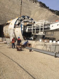
The TBM will be launched from a bell-out chamber with a 12 m high ceiling currently under construction. The Newburgh shaft features a complex logistical setup including an elaborate hoisting system designed to service the shaft. The hoisting system will provide a lifting capacity of up to 90 metric tons to be used during TBM assembly.
Robbins worked closely with KSC to ensure that TBM components were designed and sized so all parts were less than 90 metric tons and could be lifted with the contractor’s hoist system to fit down the narrow, deep shaft window. A factory acceptance test was held in February 2017 After being shipped to the site, the TBM was assembled on a moving cradle at the bottom of the shaft, and then moved to the tunnel face.
In August 2019, The NYCDEP completed excavation of the Delaware Aqueduct Bypass Tunnel, a significant milestone in the USD $1 billion effort to repair leaks in the longest tunnel in the world. The TBM broke through a wall of shale bedrock nearly 700 feet (210 m) below the surface. Excavation of the tunnel was completed on budget and ahead of schedule.
Bahce-Nurdag High Speed Rail Tunnels
Robust Single Shield Navigates Turkey’s Hardest Rock
Project Overview
 Gaziantep province, in Southeastern Turkey, is an important center of agriculture and trade divided into nine districts. With a population of nearly 1.7 million, the province is overhauling its public transportation with a rail line between the town of Bahçe and the Nurdağı district. The Bahce-Nurdag Railway Tunnel will consist of two parallel 10.1 km (6.3 mi) tunnels, excavated by both drill and blast (2.9 km/1.8 mi) and TBM (7.2 km/4.5 mi).
Geology
The complex geology of the region is affected by the East Anatolian Fault zone, making ground conditions unpredictable. Mixed ground conditions prevail on the project, and range from interbedded sandstone, quartzite, and mudstone to highly weathered shale and dolomitic limestone. High water ingress is predicted with several springs directly overhead.
Machine Design
The customized Single Shield TBM was designed with Difficult Ground Solutions (DGS). Closure gates and an emergency sealing system effectively seal off high-pressure inrushes of water. The system reduces or eliminates the amount of mud or water that can pass through the machine and gives the crew time to safely grout off the water inflows. During such an event the machine would be stopped until water inflows are reduced to the point that the TBM could begin excavation once again.
Onsite Assembly & Excavation
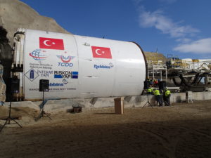
The Single Shield TBM was assembled at the jobsite using Onsite First Time Assembly (OFTA). The jobsite location about 20 miles (32 km) from the Syrian border complicated shipping of some parts but the assembly was completed and a launch ceremony held in January 2016.
The TBM encountered a very high strength rock mass—perhaps the highest strengths yet encountered in Turkey. Samples of meta-sandstone and meta-mudstone have tested at 223 Mpa UCS.
Breakthrough
On July 24, 2020 the first TBM-driven portion of tunneling was completed. The 8.9 km (5.5 mi) long tunnel that was excavated had some of the hardest and most abrasive rock encountered in Turkey. The TBM achieved up to 456 m (1,500 ft) per month, a result achieved with the help of a Robbins Continuous Conveyor System for muck removal.
Dulles Airport Train System
Swift Single Shields Excavate Dulles Airport
Project Overview
 With more than 27 million passengers a year, the Dulles International Airport is one of the busiest hubs in the country. The Metropolitan Washington Airports Authority, project owner, created a scheme to maximize transportation efficiency at the airport via an extensive subway system. The new rail line, called the Airport Train System (ATS), was designed to eliminate the previous system of rubber-tired surface vehicles, which added to airport congestion. The USD $1.2 billion project includes a fleet of 29 rail cars capable of traveling up to 68 km/hr (42 mph) between stations.
While excavated using a variety of methods, a 560 m section needed to be TBM-driven due to the location of an active concourse directly overhead. The Atkinson/Clark/Shea JV, contractor for the twin tunnels, awarded a complete contract to Robbins in 2004for two 6.4 m (21.1 ft) diameter TBMs, back-up systems, cutters, and spare parts.
Geology
The tunnel passed through mudstone, sandstone and siltstone geology from 32 to 48 MPa (4,700 to 7,000 psi) UCS. Conditions in the tunnel required immediate grouting at the tail shield to limit settlement.
TBMs
The owner specified Single Shield TBMs due to the short tunnel lengths, tunnel lining requirements, and immediate grouting requirements. Robbins refurbished the Single Shield TBMs, which were originally built in 1985 for the Taipei Metro Subway. Each machine received a new cutterhead, back-up system, thrust controls, and segment erector.
The machines were fitted with 15″ diameter disc cutters to bore in relatively soft rock. The back-up system was designed as an open gantry system for single-track muck cars.
Tunnel Excavation
 Each of the TBMs bored two tunnel drives, 460 m and 100 m (1,500 ft and 335 ft) in length. The TBMs bored the first 460 m (1,500 ft) section and were then walked through the 180 m (600 ft) long Concourse B station, excavated by cut and cover, to their second heading. While the TBMs bored, precast concrete segments were erected within the TBM tail shield to form the tunnel lining. Both TBMs had to maneuver through sharp turns with radii of 125 m (410 ft) as they approached the Main Terminal.
The machines broke through in September 2006. Many other methods including the New Austrian Tunneling (NATM) method and digger shields were used on the project as well. Phase 1 is slated for completion in 2009 and will provide rail service from both Concourse B and Concourse C to the main Terminal.
Theun Hinboun Expansion Project
Project Overview

The Theun Hinboun Expansion Project is a hydroelectric project that requires a 5.5 km (3.4 mi) headrace tunnel bored by a Robbins Single Shield TBM – the first instance of TBM-driven tunneling in the country of Laos. Located on the banks of the Nam Theun River, the project consists of a new station, dam, and headrace tunnel which will add electricity supplies to Laos and neighboring Thailand by 2012. The USD $270 million project will address the power needs of the two countries by adding an additional 280 MW annual generating capacity. The original plant, built by Recchi-CMC JV between 1995 and 1998, already produces 220 MW annually. Power will be shared, with approximately 220 MW going to Thailand and 60 MW to the Laotian national power company, Electricite du Laos (EDL). The project also promises to improve the supply of electricity in Laos by extending the 115 kV transmission grid to the project area and increasing power supply to the existing grid.
Single Shield TBM Design
On December 22, 2008, CMC di Ravenna signed a contract with Robbins to provide a 7.6 m (15.1 ft) diameter Single Shield TBM. The TBM was assembled at Robbins’ Solon manufacturing facility in Ohio and shipped to the jobsite along the Nam Theun River. CMC di Ravenna chose the Robbins Single Shield for its short shield length, based on the geology and the need for continuous tunnel lining.
The Robbins TBM was designed to accommodate moderate squeezing ground conditions. Ground along the tunnel alignment consisted of alternating strata of sandstone, siltstone, and mudstone. An articulating cutterhead with overcutters allowed the machine to excavate 100 mm (4 in) beyond the nominal tunnel diameter. To support the ground and provide final lining, 280 mm (11 in) thick, pre-cast concrete segments were used in a 5+1 arrangement, making a finished tunnel diameter of 6.9 m (22.6 ft).
TBM Excavation
 During excavation, the Robbins Single Shield TBM averaged 19 m (62 ft) per day, with a peak advance rate of 37 m (121 ft) in one day. Ground conditions consisted of fair to good rock for 95% of the tunnel length, with some sections of poorer rock quality.
Challenging conditions included an anticipated 15 m (50 ft) wide fault zone at about the 4,700 m (2.9 mi) mark with flowing water. The crew was able to drill a borehole and use expanding foam to consolidate the ground, allowing boring to continue. The machine broke through on schedule, on November 21, 2010.
The Pajares Lot 4 tunnel
Project Overview
 The Pajares Lot 4 tunnel is part of Spain’s AVE high-speed rail link. The entire 49.5 km (30.8 mi) long tunnel connects Asturias to the Madrid-Valladolid high-speed link. The route was divided into four lots, with two tunnels for traveling both east and west.
Project owner, Administrador de Infraestructuras Ferroviarias (ADIF), awarded the construction contract for Lot 4, a 10.5 km long section of tunnel, to a joint venture of Constructora Hispanica, Azvi, Brues y Fernandez and Copcisa. The joint venture chose a 10 m (32.8 ft) diameter Single Shield TBM to bore the tunnel. The TBM was designed by Robbins and built by Mitsubishi Heavy Industries. The machine was pre-assembled at a shop in Spain and final assembly was completed onsite.
Geology
The machine began boring in August 2006 through sandstone, shale, limestone, molasse, and volcanic rocks with Unconfined Compressive Strengths (UCS) of 40 to 90 Mpa (6-13 ksi). Robbins’ Single Shield design allowed the machine to cope with this fractured and varied rock. The machine could also erect 500 mm (19.7 in) thick pre-cast concrete segments to support the tunnel walls in troublesome geology.
TBM and Tunnel Excavation
 The TBM featured 17 inch (432 mm) cutters and was powered by 5,180 kW (6,946 hp) to generate a maximum cutterhead thrust of 16,814 kN (3,780,000 lb). The back-up system for the machine consisted of open gantries. Tunnel excavation was completed in July 2009.
La Réunion Irrigation Project
Project Overview
 The La Réunion Irrigation Project is located in a French territory in the Indian Ocean. The project consists of a system of tunnels that irrigates sugar cane crops and provides water to the general population on the island’s west side. Underground tunnels transport water from three sources on the island’s water-rich east side to more arid western areas. Several organizations financed the project, including the European Community, the French Government, the Réunion Department and the Réunion Region.
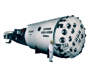
In 1990, French Contractor SOGEA awarded the TBM contract to Robbins. The company built a 4.3 m (14.1 ft) diameter Single Shield tunnel boring machine (TBM) for the boring of Tunnels I and II. Tunnel I carries the combined inflow of water from Tunnels II and III and river water from the Rivière de Galets. This water is then transported 8.6 km (5.3 mi) to a reservoir on the western side of the island. Tunnel II is a short 2.4 km (1.5 mi) tunnel that carries the water from Tunnel I via siphon under the Rivière de Galets.
Geology
Geology in all three La Réunion tunnels consisted mainly of olivine basalt. Faults in the region have created brecciated zones of blocky rock combined with mudstone and clay. Water inflows and alterations are typical of these zones.
TBM
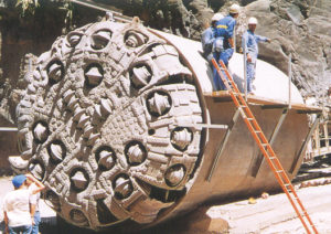
Robbins designed the Single Shield TBM to meet the unique challenges of abrasive rock and water inflows in the two tunnels. The machine’s cutterhead featured five buckets and 29 recessed back-loading 17 inch (432mm) disc cutters mounted for safe changing from the rear.
Six 160 kW (214.5 hp) motors powered the cutterhead and generated over 1,297,547 N-m (960,177 lb-ft) of torque. The two-speed articulated cutterhead increased direction control and stability in blocky rock. Robbins also added a pumping system to the TBM and seals to the cutterhead and shield. These added features prepared the machine for boring through basalt with heavy water inflows.
The TBM’s ventilation system included a 900 mm (35.4 in) diameter fan, an air duct, an air conditioning unit and a cassette system control-mounted on the TBM back-up.
Tunnel Excavation
 In Tunnel I, the TBM met its first challenge at the outset. The initial 500 m (1,640.4 ft) of the drive consisted of hard volcanic debris, water, and blocky rock. The TBM encountered two extensive zones of poor rock with maximum water inflows into the tunnel of approximately 45 liters (11.9 gallons) per second. The crew and Robbins field service engineers dealt with these problems with several on-site modifications. One of these modifications involved removal of the extendable cutter to allow installation of an extra bucket in the face. This extra bucket increased the number of openings and improved face cleaning operations, leading to more efficient tunnel boring.
During boring, the wear on the cutter assembly hubs was severe due to the soft but highly abrasive olivine basalt. This problem was partially resolved by the tunnel crew who decided to hardface the hubs. Cutter ring wear varied from 300 hours of life for center cutters to 50 hours of life for gauge cutters in the most abrasive conditions.
Despite difficult geologic conditions, the TBM continued to make significant advances and finished on schedule. The machine advanced at an average rate of 4.46 m (14.6 ft) per hour. An average workweek consisted of five days in three shifts, totaling 1,989 machine hours.
The TBM achieved breakthrough in Tunnel I on September 17, 1992 and then underwent a routine rebuild and testing for Tunnel II. The machine began boring the second tunnel in 1993 and finished in six months.