 Close
Close  Menu
Menu 
Project Categories: Main Beam TBM
San Vicente
Project Overview
 The San Vicente Pipeline, 17.7 km (11 mi) in length, connects the San Vicente Reservoir in Lakeside, California to the San Diego County Water Authority Second Aqueduct. The pipeline is part of the Water Authority’s Emergency Storage Project that will provide water to the city in the event of a drought or major earthquake.
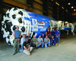
Project owner San Diego County Water Authority awarded the construction contract to the Traylor-Shea joint venture. The contractor chose a 3.5 m (11.5 ft) diameter Robbins Main Beam TBM and back-up system for two sections of tunnel at opposite ends, totaling about 2.75 km (1.70 mi) in length.
Geology
Due to the varying geology, multiple tunneling methods were chosen for the project. Two open-face digger shields were chosen to mine in conglomerates, while the TBM is mining in sections of rock at either end of the tunnel. The TBM-driven pass through granitic rock geology with a UCS of 140-345 MPa (2050 si).Drill and blast excavation is also being used in sections that interface the rock and conglomerate.
TBM
The refurbished TBM features 17 inch (432 mm) cutters and can generate a thrust of 6,005 kN (1,350,000 lb). The machine also has a maximum torque of 1,056,546 N-m (779,268 lb-ft) at the cutterhead. The Robbins back-up system consists of 11 decks and muck is being removed via muck cars.
Tunnel Excavation
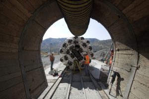 Boring began on June 21, 2006 after an onsite TBM assembly of only 30 working days. The machine excavated a 1.2 (0.7 mi) section west of the San Vicente Portal. and was then slated for an additional 400 m (1300 ft) section in weathered granite with clay seams. The Traylor-Shea JV slowed rotation of the cutterhead in order to bore through the mixed face and avoid clogging of the muck buckets. Excavation of the section using the TBM, rather than drill and blast, saved approximately 120 days on the construction schedule. The machine was then removed and re-launched at the West shaft where it will bore 1.3 km (0.8 mi) east. The machine excavated in granite requiring steel ribs and rock bolts, and completed its second section in April 2008.
Plateau Creek
Project Overview
 The Plateau Creek Pipeline was built to replace a pre-existing pipeline that supplied fresh water to rural and urban areas of Mesa County, Colorado, USA. The new tunnel provides water to 70,000 customers and has four times the hydraulic capacity of the old pipeline, which was unable to meet the District’s peak water demands.
The project owner, UTE Water Conservancy District, awarded the construction contract for the entire 21 km (13 mi) pipeline to the Barnard-Affholder Joint Venture. Affholder was solely responsible for the two sections of tunnel that were bored by TBM. The contractor used a 3.3 m (10.8 ft) diameter Robbins Main Beam TBM to bore two tunnel lengths of 1.0 km (0.6 mi) and 3.1 km (1.9 mi).
Geology
The geology consists of sandstone, shale and siltstone with an Unconfined Compressive Strength (UCS) of 69 – 172 MPa (10 – 25 ksi). The rock required immediate support including rock bolts, wire mesh, and shotcrete.
TBM
Robbins rebuilt and modified the Affholder-owned Robbins Main Beam TBM specifically for the project. The machine had been a workhorse for Affholder, who has used the machine on nine different projects totaling over 30 km (19 mi) since purchasing the machine in 1993.
Modifications included a new cutterhead, cutterhead power increase by 25%, a new high capacity main bearing and a thrust increase to allow a loading of 267 kN (60,000 lb) per cutter. The machine was capable of up to 4,893 kN (1,100,000 lb) of cutterhead thrust and could generate up to 455,738 N-m (336,135 lb-ft) of torque at the cutterhead.
Tunnel Excavation
 Boring began on the 1 km (0.6 mi) long tunnel in June 2000 and the machine holed through in August, just 1 month later. The machine was then disassembled and re-launched in only 2 weeks to bore the longer 3.1 km (1.9 mi) tunnel.
Excavation on the second tunnel began in September 2000. The machine set a world record in its size class on September 14th when it advanced 67 m (219 ft) in a single eight-hour shift. The TBM holed through ahead of schedule on March 16, 2001.
Meråker
Project Overview
 The Meråker Project consists of a system of power stations and underground tunnels that increase the electrical output supplying a local smelter and surrounding areas. Three lakes and several rivers supply 44 km (27.3 mi) of tunnels that feed into a generating facility in Tevla. From Tevla, a combined headrace/tailrace tunnel carries the water to the power station at Meråker.
Merkraft, a joint venture of Eeg Henriksem Anlegg a/s and a/s Veidekke, chose a Robbins 3.5 m (11.5 ft) diameter Main Beam tunnel boring machine (TBM) to bore 10 km (6.2 mi) of tunnel at Meråker. The remaining sections of tunnel were excavated by drill and blast.
Geology
Rocks along the tunnel path consist of Cambrian and Ordovician metamorphic sediments with meta gabbro intrusions. In all, six different rock types exist along the tunnel route. These rocks include relatively soft phyllite; mixed face rocks such as greywacke and sandstone; and hard meta gabbro.
TBM
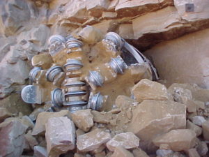
Robbins built the Main Beam TBM to successfully bore through varying rock conditions—from hard to mixed face. The machine featured four 335 kW (459 hp) motors and 25 front-loading disc cutters 19 inches (483 mm) in diameter. The TBM had cutterhead power of 1,340 kW (1,836 hp) and a maximum cutterhead thrust of 10,291 kN (2,313,531 lb).
The High-Power TBM was a stronger, more durable TBM than its predecessors. It was one of the first TBMs of a line that Robbins developed to withstand higher loads. These machines ushered in the new generation of TBMs with features such as triple axle main bearings and cutterhead modifications to improve boring efficiency at high thrust.
Tunnel Excavation
The TBM began boring at an impressive rate in September 1991. In its first full month of boring, the TBM excavated 1,029 m (3,376 ft). Soon after, the machine set a Norwegian tunneling record of 395 m (1,295 ft) during the week of October 28-November 3, 1991. During the course of the drive, the TBM reached rates of penetration up to 10 m (32.8 ft) per hour. Its average rate of penetration was 6 m (21 ft) per hour or 253 m (830 ft) per week. The machine’s best day was 100 m (329 ft), its best week was 427 m (1,400 ft), and its best month was 1,358 m (4,455 ft). The TBM accomplished these high advance rates despite Norwegian regulations limiting underground construction projects to 100 shifts per week.
In 1992 the TBM finished the 10 km (6.2 mi) tunnel six months ahead of schedule. The early completion allowed workers to finish all 44 km (27.3 mi) of tunnel in late 1992.
Chicago's Tunnel and Reservoir Plan (TARP)
Thirty TBMs participate in Chicago’s Epic Tunnel and Reservoir Plan (TARP)
Project Description
 Spanning 20 years and using over 30 TBMs, Chicago’s massive Tunnel and Reservoir Plan (TARP) has been possibly the largest clean water project of the twentieth century. The TARP was created in 1975 to combat increased flooding and drainage problems that plagued Chicago and surrounding areas. After heavy rains, combined sewage overflows (CSOs) would seep into residential basements, nearby streams and rivers, as well as Lake Michigan – Chicago’s main source for drinking water. TARP was originally divided into two phases but now refers solely to Phase I.
Phase I
Phase I was directed towards pollution control and consisted of tunnels, drop shafts, and dewatering stations to eliminate nearly 85 percent of CSO pollution. Four tunnel systems comprise the first phase: Mainstream, Des Plaines, Calumet and O’Hare, which have a combined length of 176.1 km (109.4 mi) and range in diameter from 2.4 m to 10.8 m (8.0 ft to 35.4 ft). Nearly all of the tunnels were excavated in the area’s dolomitic limestone, and required the use of TBMs up to 10.8 m in diameter—the largest TBMs that had ever been built at the time.
 The Mainstream Tunnel System was composed of 65.2 km (40.5 mi) of tunnel, the Des Plaines System with 41.2 km (25.6 mi), the O’Hare System with 10.6 km (6.6 mi), and the Calumet System of 59.1 km (36.7 mi). A later tunnel for the Little Calumet Leg of the Calumet system was excavated using a Robbins TBM in 2002, setting multiple records in the process including 138 m (452 ft) bored in one day. Immediately upon completion, each tunnel system was put into service and the benefits were seen almost instantaneously. After more than 30 years and over 160 km (100 mi) of tunnels, the entire first phase of the TARP system became operational in 2005.
Phase II
Phase II, now called the Chicago Underflow Plan (CUP), consists of three main reservoirs: the Majewski Reservoir, Thornton Reservoir, and McCook Reservoir with a combined capacity of 69.05 billion liters (18.24 billion gallons). The reservoirs are a joint project of the Water Reclamation District and the U.S. Army Corps of Engineers, built to provide flood relief by storing the water collected and transferred from the TARP tunnels until it can be treated at local reclamation plants.
Excavation and Breakthrough
Construction on the Majewski CUP Reservoir was started in 1990 and finished in 1998, with a capacity of 1.29 billion liters (342 million gallons). The Thornton Reservoir was divided into two stages, including a transitional reservoir completed in 2003, and a permanent CUP reservoir completed in 2015. The permanent CUP reservoir has a capacity of 29.9 billion liters (7.9 billion gallons) and provides an estimated $40 million annually to 15 communities. Finally, the McCook Reservoir, also planned as a two-stage build, will provide storage of up to 38 billion liters (10 billion gallons). The first stage was completed in 2017, while the completion date of the second stage is scheduled for 2029. To date, the reservoirs have yielded hundreds of millions of dollars in flood damage reduction benefits.
The TARP program has won numerous awards and honors over the years from the local and federal EPA, as well as the American Society of Civil Engineers award in 1986 for the most outstanding civil engineering project. The tunnels and reservoirs have resulted in a dramatic improvement to water quality in Lake Michigan, and have eliminated CSO overflows. Fish and wildlife have returned in recent years to local rivers and to Lake Michigan, and the waterfront property is becoming more attractive to businesses and the general population alike.
Pahang Selangor Raw Water Tunnel
Trio of TBMs bore Malaysia’s Largest Infrastructure Project
Project Overview
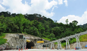
 The Pahang Selangor Raw Water Tunnel, for the Malaysian Ministry of Energy, Green Technology, and Water, conveys raw water from the Semantan River in Pahang to the South Klang Valley area of Selangor state. The three tunnels, totaling 44.6 km (27.7 mi), address projected water shortages due to the area’s rapidly growing population. The tunnel transfers 27.6 cubic meters (7,300 gallons) of water per second to a new treatment plant. The drinking water supplies about 7.2 million people.
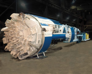
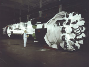
The SNUI JV, consisting of Shimizu Corporation, Nishimatsu Construction, UEM Builders Bhd, and IJM Construction, chose three Robbins 5.23 m (17.2 ft) diameter Main Beam TBMs to excavate the three sections of the tunnel. The total supply included back-up systems, continuous conveyors, cutters, spares, and field service personnel.
Ground Support and TBM Design
Tunneling took place in high cover conditions, up to 1,200 m (3,900 ft) below the Titiwangsa mountain range. Geology during the initial stages of advance consisted of hard, abrasive granitic rock up to 200 Mpa (29,000 psi) UCS. The tunnels were supported with ring beams, rock bolts, and shotcrete depending on the conditions. If unstable ground was encountered, invert thrust systems could be utilized to avoid gripping against the tunnel walls.
To successfully excavate the hard rock, each High Performance (HP) TBM was fitted with 19-inch (482 mm) back-loading disc cutters- making them the smallest diameter back-loading cutterheads ever provided. The cutters were carefully monitored for wear using remote monitoring systems. The wireless systems allowed the crew to plan cutter changes and keep track of wear by recording several variables on each cutter, including cutter rotation (which is computed to percentage wear), temperature, and vibration. Each 19-inch face and gage cutter was equipped with a sensor bolted inside the cutter housing, allowing raw data to be sent to a program display in the operator’s cabin.
Tunnel Excavation
 The first machine was launched on November 10, 2010, followed shortly after by the second on December 30, 2010. The third machine began boring in March 2011 and all three machines are currently boring as scheduled. All of the machines were assembled outside their particular adits, then “walked” down a 6-10% grade to an NATM-excavated starter tunnel. Two of the machines were launched with a shortened back-up configuration of 10 decks and a temporary transfer conveyor, while the third for logistical reasons utilized trucks for muck removal in the preliminary boring phase. Once the machines had advanced about 100 m (330 ft), the remaining back-up decks and permanent Robbins continuous conveyor were then installed, due to the adit configurations.
During the initial stages of advance, the machines achieved rates of up to 3.5 m (11.5 ft) per hour, leading the three machines to excavate over 1,400m (4,600 ft), 540 m (1,800 ft) and 330 m (1,100 ft), respectively by April 2011. As each TBM continued on its 11km (6.8 mi) run, the machinery had to overcome adversity including blocky rock, over-break, power outages and water inflows.
The machines maintained excellent advance rates throughout the project despite many challenges. Due to the hot springs the machines were boring under, water ingress at temperatures up to 56 degrees Celsius was recorded. Maximum rates of 49 m in one day, 198 m in one week, and 657 m in one month were nonetheless achieved.
Among other methods of ground support used during boring, the near-zero rebound fiber mortar (sprayed shotcrete) is the primary method being used during the Pahang Selangor Project. This marks the first time this method has been used outside of Japan. The success of this innovative implementation has been proven through reduced project downtime, dust reduction and good bonding.
Breakthrough
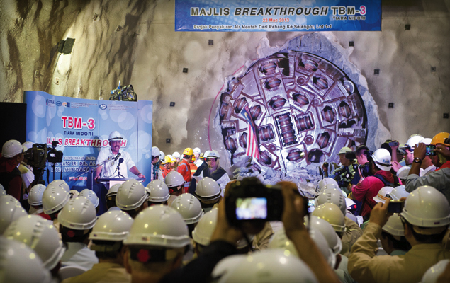
 The first of three 5.23 m (17.2 ft) Main Beam Robbins TBMs broke through at the Pahang Selangor Raw Water Tunnel on March 22, 2013 to a large ceremony of cheering onlookers. The breakthrough was attended by dignitaries, contractors and honored guests, with everyone very enthusiastic about the machine’s success.
The two remaining 5.23 m (17.2 ft) machines met in the middle of the tunnel in mid-February 2014. It was a moment worthy of celebration; marking the completion of the longest tunnel in Southeast Asia.