 Close
Close  Menu
Menu 
Project Categories: Main Beam TBM
Galerie des Janots
Project Overview
Galerie des Janots is one of the fourteen operations designed to save water and protect resources, which were carried out by the Aix-Marseille-Provence metropolis, water agency Rhône Mediterranean Corsica, and the French State Government. The Janots gallery improved access to water in communities east of the Aix-Marseille-Provence 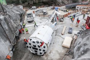 metropolis (Cassis, Roquefort-la-Bédoule, La Ciotat and Ceyreste). The pipeline replaced existing pipelines—located in a railway tunnel—which had significant safety and vulnerability deficiencies with estimated water losses of 500,000 cubic meters (17.7 million cubic ft) per year. The prior pipes had a capacity limited to 330 liters (87 gal) per second, which was largely insufficient in the summer season. The objective of the Galerie des Janots operation was to increase capacity to 440 liters (116 gal) per second.
Geology
The tunnel passes under Le Parc National des Calanques with cover between 15 m (49 ft) and 180 m (591 ft). Geotechnical studies of the area showed that the 2.8 km (1.7 mi) long tunnel was shown to have limestone, groundwater, and both filled and empty karst cavities. One of the biggest challenges faced by the excavation was two uncharted caverns; the largest of the two measured a staggering 8,000 cubic meters (283,000 cubic ft) in size.
The Machine
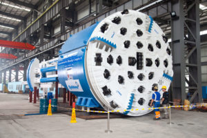
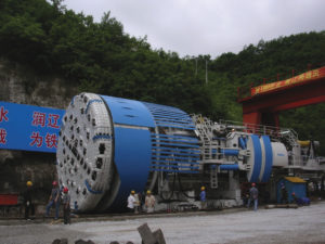
On March 3, 2017, the 3.5 m (11.5 ft) diameter Robbins TBM, christened “Augustine”, was commissioned. This TBM was extensively modernized and upgraded during the rebuild for the Galerie des Janots project in La Ciotat, France. At 250 metric tons (276 t), and 135 m (443 ft) long, the TBM and backup system could not fit at the small jobsite adjacent to residences and other buildings. Very little on-site storage was allotted in the launch area, with just 25 m (82 ft) outside the portal for assembly, which was the exact length of the TBM from the head to the rear legs. This made the logistics of the machine arriving in sequence and being assembled on time vital.
The crew did a two-stage assembly for the machine, first assembling the TBM and five decks of the backup system, with the remaining decks afterwards. After assembly, the crew launched the machine, working 24 hours daily to excavate the tunnel and maintain equipment during the bore.
Excavation
When the machine launched, optimism was the crew’s mindset about getting through the karstic limestone obstacles. While limestone itself is easy to maneuver through, challenges emerged with the karst. For this project, the TBM was equipped with a probe drill, and to further identify cavities ahead of the TBM the crew installed a geotechnical Bore-tunneling Electrical Ahead Monitoring (BEAM) system. BEAM is a ground prediction technique using focused electricity-induced polarization to detect anomalies ahead of the TBM.
However, despite all the preparation, for the first 1,000 m (3,280 ft) of the bore, ground conditions were difficult. Limestone with powdery clays was encountered, which became an obstacle when groundwater was added into the equation. In some areas, there was water bearing rock encountered, which turned the material into a sticky clay. This material blocked the cutterhead; however, this was solved by unblocking the cutterhead manually using a clay spade and shovel. When torque spiked, the crew could tell blocking had occurred. Reducing water sprays through the cutterhead helped to avoid creating sticky clay.
The weak rock and clay conditions necessitated ground support including resin-anchored bolts and rings in bad ground, topped with wire mesh and a 10 cm (3.9 in) to 15 cm (5.9 in) thick layer of shotcrete. Some small filled and empty karst cavities were encountered, and these were systematically drained if needed and filled with grout or foam.
When the crew hit the 1,035 m (0.6 mi) mark, they hit a cavern on the TBM’s left side. The cavern was studded with stalactites and stalagmites and measured 8,000 cubic meters (283,000 cubic ft) in size. The crew named this cavern “grotte Marie Lesimple” after their site geologist.
In order to pass by the cavern, the crew had to erect a 4 m (13 ft) high concrete wall so the TBM would have something to grip against. A small door allowed access inside the cavern, which had formed naturally at a point 60 m (200 ft) below the surface. The TBM was then started up and was able to successfully navigate out of the cavern in eight strokes without significant downtime to the operation—the process took about two weeks.
While karst cavities were a known risk during the bore, the cavern was not shown in vertical borehole reports or in the geophysical survey conducted from the surface along the alignment.
Breakthrough
After clearing the cavern, the ground stabilized. The machine averaged excavation rates of 20 m (66 ft) to 22 m (72 ft) per day in two shifts, with a dedicated night shift for maintenance. For five days per week, crews ran the excavation, even achieving over 400 m (1,312 ft) in one month. This performance continued steadily until the 2,157 m (1.34 mi) mark, when the machine grazed the top of an unknown cavity that extended deep below the tunnel path. This structure measured 22 m (72 ft) long, 15 m (49 ft) wide, and 14 m (46 ft) deep, or about 4,500 cubic meters (159,000 cubic ft) of open space.
Crews probed in front of the cutterhead and began working to stabilize and secure the cavity with foam and concrete, while also excavating a bypass gallery. The biggest difficulty after filling most of the cavity was ensuring the gripping of the machine–six bypass galleries and four months of work were required for this. For the last 600 m (1,970 ft) of tunneling, the rates averaged 18 m (59 m) per day in two shifts, and a max rate of 25 m (82 m) in one day.
In April 2019, the 3.5 m diameter Main Beam TBM and its crew finally broke through at the Galerie des Janots Tunnel in La Ciotat, France. The tunnel itself was full of arduous obstacles, however the lessons learned from it were invaluable and paramount.
Thuong Kon Tum Hydroelectric project
Project Overview
Vietnam’s Thuong Kon Tum Hydroelectric Project is a 17.4 km tunnel that may well be the longest in the country. The completed conduit was designed to draw water from the Dak Nghe River to supply electricity to the Central Vietnam region via a 350 MW capacity power station. This project 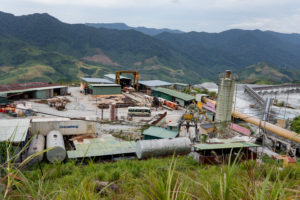 encountered numerous challenges, from the geology to the original contractor. A 4.5 m diameter Main Beam TBM excavated a section of the tunnel in granite rock up to 250 MPa UCS. The TBM was originally launched in 2012, though non-satisfactory performance led to the original contractor leaving the site. The revamped project launched in 2016 with a new contractor and Robbins leading the refurbishment and operation of the TBM.
Geology
Originally the geology of the project was noted as a granite rock type with strengths up to 120 MPa UCS. However, the available geology of the project was extremely limited with factors being the mountainous jungle above the tunnel making scouting extremely expensive and complicated. In this area rainfall is torrential during monsoon season with annual precipitation averages of 1800 mm. There were also landslides, which blocked roadways and left travelers without detours to their destination. These difficulties led to Onsite First Time Assembly (OFTA) being used to allow shipments to arrive in smaller pieces.
Machine Refurbishment
In 2012 the 4.5 m diameter Robbins Main Beam TBM and Continuous Conveyor System were supplied to bore a 10 km section of the tunnel.
In 2016 a joint venture with Robbins and a Vietnamese contractor, Construction Joint Stock Company No. 47 (CC47), was awarded the contract to refurbish the TBM, which suffered damage from lack of maintenance and the tropical climate (ambient air temperatures in tunnel hovered above 30 degrees Celsius, with humidity at a constant 90 percent or higher). The contract was also to excavate the remaining tunnel.
In March 2016, the refurbishment to the TBM and equipment began. This included repair to several kilometers of tunnel conveyor belting and components, rock support systems, and all motors on the equipment. Guidance Systems and VFDs also needed to be recommissioned. With the high humidity being a factor, main bearing conditions were observed and detailed tests were conducted; results showed the main bearing chamber had not been contaminated.
Equipment testing began in April 2016, to adjust the boring conditions to cope with the exceedingly hard rock (tested at up to 300 MPa UCS). Over the next few weeks, the machine’s progress skyrocketed with it being shown the equipment could handle the terrain after sitting idle.
Excavation
In June 2016, the TBM began boring after the two months of intensive repairs. Day to day operations for the tunnel and training of personnel were conducted by Robbins, while the contractor provided services to the tunnel such as ventilation, water, power, rail lines, ring beams, and other materials. The machine was able to bore 17.5 m per day for three days constantly, eventually surpassing those expectations.
The crews expected to pass through about 10 percent type 1 faults, and 65 percent class three faults. The rock mass was expected to consist of 10% Type 1 (massive, competent), but it was around 75 to 80 percent of the bore. The granitic rock was highly massive with few fractures and jointing. The compressive strength of the rock was estimated at 170 MPa, but it averaged 270-290 MPa.
The disc cutters used were able to keep the TBM progressing. Mostly heavy-duty cutters were used with each disc ring lasting for 500 to 600 m.
Complications arose throughout the bore. The remote environment had arduous tunnel conditions such as temperature and fault zones. There were numerous amounts of faults. Boring through granite, the typical advance rates were between 2.3 and 2.5 m an hour, and between 400-500 m per month. Besides the fault zones there were three major influxes of water, which required a steel sheet to divert water to the invert, then a ring beam and McNally system was installed. The TBM equipped with McNally pockets in the roof shield allowed for steel slats or rebar to be extruded and installed as the TBM advanced. By replacing the roof shield fingers on a Main Beam TBM, the McNally system prevents movement of loose rock in the critical area immediately behind the cutterhead support. 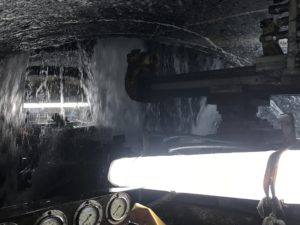
Fracture zones were not that common; the TBM passed through the major faults that discharged heated water at a rate of 600 liters/second draining naturally from the graded tunnel but made the excavation difficult. These fault zones required steel water diversion plates and drainpipes installed to direct the extreme water ingress.
Crews had a probe drill that could be mobilized quickly if grouting needed to be done ahead of the TBM. Regular face mapping was done ahead of the TBM to determine how ground conditions were changing.
By Spring 2018, there was only about 2.8km (1.7mi) of tunnel remaining. With less than two years of operation the tunnel went from 15 percent complete to 85 percent complete. The tunnel conveyor system had an availability of 93 percent, meaning that it only had seven percent downtime. Despite the successfulness of the bore, challenges still arose. Thunderstorms and power cuts wreaked havoc causing production to slow down. The geological report also predicted more fault zones in the tunnel path with an incredibly large zone near the last 500 m of a tunnel.
Breakthrough
In the last quarter of 2018, crews hit a large fault zone, 250 m away from where the TBM would meet the downstream Drill-and-Blast excavated portion of the tunnel. Upon encountering the fault, the tunnel was inundated with water and debris with an estimated volume of 1,200 cubic meters. The resulting cavern was unstable and directly in the bore path causing the machine to be stopped. 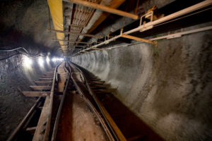
After filling the cavity and consolidating the surrounding geology with over 22,000 kg of polyurea silicate foam, the machine was able to advance forward. However, a complication emerged. When an excessive amount of loose rock was encountered, investigations discovered that the foam had not reacted and set as expected. The heat in the cavity along with the heat created by the thermal reaction of the bi-component foam had produced an environment that prevented the foam from fully expanding or setting. To complicate matters further, additional new collapses of the cavity could be heard from inside the TBM. The size of the cavern was now estimated to be more than double the original size.
The machine was pulled back from the cavity and a third-party contractor was employed to install a concrete plug between the TBM and cavity by using a concrete formwork and pumping in concrete using the TBM shotcrete system. A decision was made to remove the TBM and install the final lining.
In the last quarter of 2019, the final 250 m of tunneling was completed by a Drill & Blast team. TBM excavation rates were very good for the majority of the boring, despite all the arduous challenges that emerged throughout the process.
Mumbai Water Tunnel
A National Record in Urban, Hard Rock Conditions
Project Overview
 The Mumbai Water Supply Tunnel runs between the Kapurbawdi and Bhandup areas. The tunnel provides the city’s approximately 20.5 million residents with a reliable water supply, even during the seasonal monsoons that regularly contaminate Mumbai’s water resources. The basalt rock tunnel alleviates Mumbai’s current leakage problems from its aging lines and provide inhabitants with a consistent flow of clean drinking water.
Geology
Abrasive basalt rock and some fractured ground with potential for water inflows.
Onsite First Time Assembly
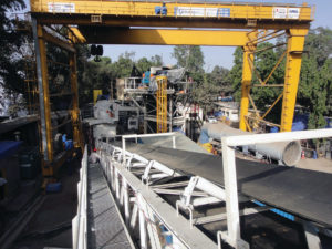
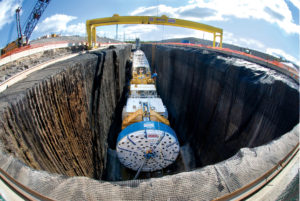
 Onsite First Time Assembly (OFTA) was used to assemble the main bearing, lube system, back-up decks and horizontal, vertical and stacker conveyors. OFTA saved the contractor both time and money by assembling the parts at the jobsite and eliminating pre-assembly at the manufacturing facility in Shanghai, China. The OFTA process took place at the shaft bottom in a 100 m (328 ft) long starter chamber and a 50 m (164 ft) long tail tunnel. TBM components were lowered into the shaft using mobile and gantry cranes.
Excavation and Breakthrough
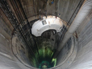
Due to the urban location of the tunnel, the TBM was launched from a 109 m (357 ft) deep shaft, and its launching sequence included an initial start-up excavation of 50 m (164 ft) with vital back-up decks connected to the TBM using cables. The first bore began March 30, 2012 and upon completion, the decks were lowered and a continuous conveyor system was installed for muck haulage and storage.
Robbins provided both the TBM and conveyor system for the project, as well as Field Service personnel to monitor the equipment and assist with daily upkeep and inspection.
 Although the machine was ultimately a success, it did experience its fair share of challenges during the 21-month bore. Difficult ground, including basalt rock, fractured ground, and water inflows, was encountered throughout the tunnel. The tunnel team took all precautionary measures and advanced slowly. The crew maintained good ventilation throughout execution and utilized consistent dewatering to deal with water inflows.
Ground support also played a critical role in poor ground: The rock support system and ring beam erector reduced downtime and stabilized rock. Challenging ground conditions, combined with the sheer depth of the 109 m (357 ft) tunnel, made the machine’s excellent advance rates a particular achievement.
By the end of TBM tunneling, the Robbins machine had reached high rates of 870 m (2,855 ft) per month and 58 m (188 ft) per day, both records for TBM tunneling in India. The contractor stated that the good rates were achieved because of “good performance of the machine and a conveyor system for muck haulage in place of conventional methods.”
West Qinling Rail Tunnels
Twin TBMs set World Records under High Cover
Project Overview
 The West Qinling tunnels are part of the Chinese Government’s Lanzhou to Chongqing Railway, a massive 820 km (500 mi) long scheme that links the capital of Gansu Province (Lanzhou) with southwestern Chongqing, a mega-city of over 35 million people. The parallel rail tunnels are for freight, and link the city of Longnan with the towns of Waina, Luotang and Fengxiang within Gansu Province. The new railway, at a cost of USD $11.3 billion, shortens transport times from 17.5 hours to 6.5 hours and enables an annual freight capacity of 100 million metric tons (110 million US tons). Trains run on the double track lines at 160 km per hour (100 mph), with a 50-train daily maximum.
In January 2009, China Railways signed a contract with Robbins for the supply of twin 10.2 m (33.5 ft) diameter Main Beam machines. The TBMs would be used to excavate two 16.6 km (10.3 mi) tunnels through the Qinling Mountains.
Geology
Geology in the two tunnels consisted of 30 to 80 MPa (4,300 to 11,600 psi) UCS sandstone and phyllite rock beneath more than 1,400 m (4,600 ft) of cover. The corresponding ground support program consisted of continuous mesh and rock bolts, with either ring beams or steel straps, for the length of the tunnel. Rather than roof shield fingers, protected mesh windows were used to install ground support immediately behind the cutterhead. In the event that extremely poor ground was encountered, the mesh pockets could be easily modified to use the McNally Support System, patented by C&M McNally Engineering of Toronto, Ontario, Canada for exclusive use with Robbins TBMs. The McNally System utilizes steel or wood slats to provide continuous support along the roof area of the tunnel, protecting workers from falling rock.
Main Beam TBMs

The two machines, for contractor China Railways 18th Bureau (Group) Co., were assembled at a local workshop and transported to the jobsites, where they were assembled on bridges spanning a deep valley. The first machine, for the Left Line, was launched at the end of June 2010 after being walked through a 2.0 km (1.2 mi) long adit tunnel. The second machine, for the Right Line, was launched on July 17, 2010. The TBM tunnels were just 40 m (130 ft) apart and located approximately 1,000 m (3,280 ft) above sea level, about halfway up Qinling Mountain.
Tunnel Excavation
The two Robbins TBMs advanced at world record rates in exceedingly difficult conditions. The first Main Beam Machine advanced 235 m (771 ft) in one week and 841.8 m (2,761 ft) in one month during Spring 2011 – rates much higher than any ever recorded for TBMs in the 10 to 11 m diameter range. The fast advancing Left Line machine also broke through into an intermediate adit tunnel on May 28, 2011 at the 5.5 km (3.4 mi) mark, where it underwent planned maintenance and inspection. Within several weeks the machine was launched again to bore the rest of its tunnel.
 Despite the conditions of phyllite and limestone with high quartz content, only about 100 cutters were changed on the Left Line TBM. The Right Line machine, launched a month later and about 1,000 m (3,280 ft) behind, also experienced good cutter wear. By 2013, both machines had made their final breakthroughs in their respected tunnels.
Svartisen Hydroelectric Project
Project Overview
 Approximately 99 percent of the total electric power in Norway is derived through hydroelectric projects, making these large schemes a key part of the country’s infrastructure. Norway’s use of hydropower dates back to 1877, when its first hydro project reached completion. By 1990, Norway had more than 170 underground hydro facilities comprising approximately 3,500 km (2,175 mi) of tunnels throughout the country. Owner-contractor Statkraft plans, builds and operates all central government hydropower plants, which produce 28 percent of Norway’s total annual hydroelectric power output. The Svartisen project, located just north of the Arctic Circle, consists of 46 shafts connected to 40 km (25 mi) of 3.5 m (11.5 ft) to 5 m (16.4 ft) diameter tunnels. The tunnels are designed to collect and carry water from the glacier-covered Trollberget Mountains to Lake Storglomvatnet, the project’s reservoir. From there, the water is fed through a 7 km (4.4 mi) headrace tunnel to a sea-level power plant at Kilvik, Holandsfjorden. There are also two gutter tunnels to catch additional water from hillside inlets.
In 1988, Statkraft contracted Robbins to supply five machines to bore 57 km (35 mi) of tunnel for the new Svartisen Hydro Project, or 62 percent of the tunnels needed for the project. Two of the machines were veteran TBMs, 8.5 m (27.9 ft) and 3.5 m (11.5 ft) in diameter, and bored 7.3 km (4.4 mi) and 15.4 km (9.6 mi) of tunnel, respectively. Also employed on the project were three new Robbins High Performance (HP) TBMs capable of high thrust loads up to 312 kN per 19 in (483 mm) cutter. These first HP TBMs were revolutionary machines that paved the way for hard rock tunneling as we know it today.
Geology
The area’s geology consisted mainly of mica schist and mica gneiss (80 percent); metasandstone (pure quartzite), granite and granitic gneiss (13 percent); and limestone and marble (7 percent). The limestone beds varied in thickness from a few centimeters to more than 100 m (328 ft). Caves and underground drainage features were evident from the surface as well. The unconfined compressive strength of the Svartisen geologic formations varied from 100 MPa to more than 300 MPa (43,500 psi). Also, the steep, uneven topography caused irregular stress on rock masses which were subject to extreme tectonic and residual pressures. Because stable, hard rock conditions were present in more than 95 percent of the tunnel, no lining was required.
High Performance TBMs
All three HP machines were equipped with 19 in (483 mm) diameter disc cutters, which were developed by Robbins for the Svartisen Project. In addition to the larger cutters, the machines were built stronger than standard TBMs and had tri-axial main bearings to withstand higher loads. The two 4.3 m (14.1 ft) diameter HP machines weighed 262 metric tons (289 US tons) and supplied 2,345 kW (3,143 hp) of power to their cutterheads, allowing each machine to reach 9,048 kN (2,034,071 lb) of thrust at the face. A conversion kit was supplied for one of the machines that allowed it to bore at 5 m (16.4 ft) diameter instead of 4.3 m (14.1 ft) and also added six cutters, bringing the total weight of the machine to 290 metric tons (319 US tons). The third HP machine, weighing 180 metric tons (198 US tons), was 3.5 m (11.5 ft) in diameter and was supplied with 1,340 kW (1,796 hp) of power to the cutterhead giving it a total 7,800 kN (1,753,509 lb) of thrust. The cutterhead featured twenty-five 19 in (483 mm) diameter disc cutters.
In addition to higher penetration rates and advance rates, the new generation of TBMs enabled efficient use of the crew. Each machine was teamed with a back-up system equipped with remote controls and television cameras, and only required a four-person crew per shift – one to operate the machine and load the rail cars, a locomotive operator, an electrician and a mechanic to handle the extension of rail, cables, ventilation and hoses.
Tunnel Excavation
 All three HP machines achieved very impressive results throughout the project. The first of two 4.3 m (14.1 ft) diameter machines excavated 6,021 m (19,754 ft) of tunnel between September 1989 and October 1990, averaging 3.8 m (12.5 ft) per hour on its first drive. In its 5 m (16.4 ft) mode, it averaged 2.74 m (9 ft) per hour. The machine had a best day advance of 75.8 m (248.7 ft), best weekly advance of 312 m (1,024 ft) and best month of 1,068 m (3,504 ft) which were all Norwegian records.
The second 4.3 m machine bored 11,861 m (38,914 ft) of tunnel between September 1989 and April 1991, averaging 3.5 m (11.5 ft) per hour. In the process, the TBM set world performance records for machines in its 4 to 5 m ( 13 to 16 ft) diameter size class: best shift of 61.2 m (200.8 ft), best day of 90.2 m (296 ft), best week of 360.5 m (1,182.7 ft) and most material excavated in 24 hours: 1,309 m3(1,700 cubic yards).
The third machine began boring in July 1990 from a junction about 4 km (2.5 mi) from the crosscut area. In May 1991, about 4,700 m (15,420 ft) into the drive, the machine experienced poor ground and water inflows which slowed excavation for about 4 months. However, despite the poor conditions, the machine still averaged an overall advance rate of 3.7 m (12.1 ft) per hour while capturing a single shift record of 55.5 m (182.1 ft).
Ceneri Base Tunnel
Project Overview
 The AlpTransit Project is a massive rail project designed to provide more efficient rail freight routes via base tunnels through the Gotthard and Ceneri mountain ranges. Currently, freight trains traveling up the mountain ranges require pushing locomotives due to steep gradients. The base tunnels will provide a route for freight trains with minimum elevation gain and will shorten passenger train times between Zurich and Milan. Some route times, such as the trip between Lugano and Bellinzona, will be cut in half with the completion of the Ceneri tunnel. The Ceneri Base tunnels and the Gotthard Base tunnels will combine to create a new rail system that will span over 70 km (43 mi) of TBM-driven tunnels and 16 years of construction. The completed rail line is expected to open to traffic in 2019.
In April 2007, Contractor Consorzio Monte Ceneri (CMC) JV – a consortium of CSC, Lugano, Frutiger SA, Thun, Rothpletz, Lienhard + Cie, and Aarau, signed a contract for a 9.7 m (31.8 ft) Robbins machine to bore a 2.4 km (1.5 mi) adit on the Ceneri Base Tunnel Project. The completed adit tunnel joins up at approximately the halfway point of the main rail tunnels. The Main Beam TBM was completely refurbished near Milan, Italy where the cutterhead diameter was changed from 7.6 m (24.9 ft) to 9.7 m (31.8 ft). The TBM was the first machine on the AlpTransit project to utilize 483 mm (19 in) cutters, designed to offer a higher cutter load and longer cutter life resulting in fewer cutter changes. The refurbished machine previously bored successfully on the main headrace tunnel of the Kárahnjúkar Hydropower Project in Iceland.
Geology and Ground Support
Rock in the area consists of schist, Swiss molasse, and Ceneri orthogneiss with a UCS of 30 to 130 MPa (4,300 to 18,800 psi). Much of the tunnel was excavated under high cover of 600 m (2,000 ft). The geology of the tunnel alignment was good for TBM boring, with no squeezing ground or large water inflows encountered. New probe drills, designed in Robbins U.S. locations, were used to verify ground conditions ahead of the TBM. Temporary tunnel support including rock bolts, ring beams and shotcrete were also used depending on geology. Excavated material was temporarily stored at a lot onsite for later preparation as rock aggregate for concrete.
Tunnel Excavation
 On November 6, 2008 excavation of the adit tunnel was completed on schedule after only ten months of boring. Only 30 cutter rings were changed during the last kilometer of boring, with the cutters excavating a combined 160,000 cubic meters (5.9 million cubic feet) of hard rock. Daily advance rates averaged 18.5 m (60.7 ft) – about 61% higher than averages achieved by similar machines boring the Gotthard Base Tunnel using 432 mm (17 in) cutters.
Olmos Trans-Andean Tunnel
PROJECT OVERVIEW

The Olmos Trans-Andean tunnel has been more than 100 years in the making, with several attempts made in the 1950’s using drill and blast techniques. The tunnel, more than 20 km (12 mi) long in total, transfers water from the Huancabamba River on the Eastern side of the Andes to drought-ridden areas on the Pacific Ocean Watershed via a tunnel bored through the continental divide. The first phase also included a 43 m (140 ft) high dam diverting the Huancabamba River near the village of San Felipe through the mountains to the dry Olmos River on the Pacific side. Once the first phase of the tunnel project was operational, the scheme supplied more than 2 billion cubic meters (500 billion gallons) of water annually for irrigation of 560 km2 (130,000 acres) of farmland. Phases that followed included two more drill and blast tunnels, two hydroelectric stations generating 600 MW each, and a canal system to filter water throughout the coast.
GEOLOGY
The machine bored in complex geology consisting of quartz porphyry, andesite, and tuff from 60 to 225 MPa (8,700 to 32,600 psi) UCS. Over 400 fault lines were present along the entire tunnel, including two major fault lines approximately 50 m (160 ft) wide.
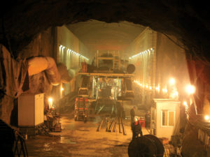
The overburden created another problem — high in-tunnel temperatures exceeded 54 degrees Celsius (130 degrees Fahrenheit). To cope with the high temperature Robbins designed the machine with a unique ventilation and air cooling system. Two interacting systems were used to cool the tunnel to 32 degrees Celsius (90 degrees Fahrenheit) or below. The high jobsite elevation (1,080 m / 3,500 ft) resulted in less dense air and less heat transfer capacity per cubic meter of air, so the two systems made it possible to blow more air into the tunnel for a maximum cooling effect.
TUNNEL EXCAVATION

Starting in late 2008, the TBM entered sections of high cover where crews experienced large overbreaks and cathedralling, along with rock bursting that could not be contained using wire mesh, rock bolts and ring beams. To better contain the fractured rock, Robbins and Odebrecht elected to make changes by installing a novel type of TBM ground support. The machine’s roof shield fingers were removed and replaced with the McNally Support System.
The McNally system works by replacing the curved finger shield plate for a curved assembly of pockets with rectangular cross-sections. The pockets extend axially from the rear side of the cutterhead to the cutterhead support, within the area where roof drills can work. Before a TBM stroke, crews slide slats of metal or wood into the pockets, such that the slats are two rows deep inside each pocket. The ends of the slats protrude from the pockets and are bolted to the roof of the tunnel using a steel strap. As the machine advances, the slats are extruded from the pockets and continuously bolted to the roof using subsequent straps. Slats are reloaded and used for the length of the tunnel to prevent deformation and rock falls.
Tunneling through the fractured and broken rock also created undue wear on the cutterhead. To cope with the problem, Robbins engineers added 19 mm (0.75 in) thick wear plates and 50 mm (2.0 in) thick square bars, known as ‘Boomerangs’, in front of each cutter. The boomerangs protect each cutter hub from blocky rock and bursting at the face.
Since modifications were done to the TBM, advance rates steadily improved, with the machine boring as much as 674 m (2,211 ft) per month. The improved rates were all the more remarkable considering two hazardous local floods in April 2008 and March 2009, which both inundated the site with more than a meter of mud and wiped out access roads.
After four years of extreme excavation through high cover and volcanic rock conditions, TBM tunneling at the Olmos Trans-Andean tunnel was completed on December 20, 2011 with an elaborate ceremony to celebrate the breakthrough.
East Side Access Project
Project Overview
 New York City’s East Side Access Project involves construction of a new subway line needed to relieve heavy traffic congestion between the boroughs of Queens and Manhattan. The line will serve approximately 160,000 commuters daily between Grand Central and Sunnyside rail stations.
Manhattan and Queens will be connected under the East River via the 63rd Street tunnel, a submersed double-deck tube. The submersed tube consists of reinforced concrete sections barged in place on the riverbed. The tube contains operational subway lines on the top deck, while the bottom deck will become operational when the East Side Access Project is completed in 2013.
Geology
The project, awarded to the Dragados/Judlau JV, is located in a range of geology from soft ground to hard rock. Twin 13.7 km (8.5 mi) long Manhattan Approach Tunnels run from the Manhattan side of the submersed tube up to Grand Central station, with geology consisting of schist, gneiss, and granite from 100 to 275 MPa (14,500 to 40,000 psi) UCS.
Equipment Features
The Robbins TBM excavated the Westbound running tunnels, consisting of four short headings that required a design allowing for swift retraction and re-launching. A second Double Shield TBM, operated by SELI, was used to excavate the Eastbound running tunnels. The Robbins High Performance (HP) Main Beam machine was designed using a segmented, bolt-only cutterhead for easier disassembly. During retraction, the outer components of the cutterhead were removed first. The shielded front section of the TBM, designed as an “umbrella”, was then retracted using hydraulic extensions. The extensions allowed the bottom, side, and roof supports to move radially inwards, reducing the machine diameter from 6.7 m (22.0 ft) when fully extended to just 6.1 m (20.0 ft) with removal of the shield assemblies.
To remove muck, Robbins designed an extensive conveyor system utilizing every commonly recognized type of belt conveyor to transport muck more than 370 m (1,200 ft) away from the jobsite. The system design involved nine separate conveyors handling muck simultaneously from the two tunnels. Two extensible fabric belt conveyors (914 mm/ 36 inches in width) traveled behind the Eastbound and Westbound TBMs, and dumped via a crown-mounted cross conveyor onto a single 1,863 m (6,100 ft) fixed-length conveyor mounted inside the submersed tube.
From the tunnel, muck was transported up the 23 m (75 ft) deep Queens shaft using a fixed-length, steel cable vertical conveyor. Once the muck reached the top of the shaft, it was transferred to the Rail Yard using three overland conveyors and a radial stacker. The second overland conveyor, 37 m (120 ft) in length, crossed Northern Boulevard, a major thoroughfare in Manhattan. This conveyor was designed as a completely enclosed box truss to eliminate debris from reaching the roadway, and sat approximately 6 m (20 ft) above Northern Boulevard and under pre-existing rail lines. Muck was then transferred from the overland conveyors to a radial stacker in the Sunnyside Rail Yard. The radial stacker rotated through 60 degrees to deposit muck in kidney-shaped piles with a capacity of 8,400 cubic meters (11,000 cubic yards).
Tunnel Excavation
 The Robbins machine made four drives, totaling 5.2 km (3.3 mi) beneath Manhattan. The machine first bored 2.3 km (1.5 mi) towards Grand Central Station, and was then retracted 2.0 km (1.2 mi) through the newly bored tunnel, leaving all tracks and tunnel support structures in place. The machine was re-launched at a “Y” shaped intersection to bore three more tunnels at varying elevations.
Boring on the first tunnel commenced on September 30, 2008 with a total of 907 boring hours, and the second, 540 m (1,770 ft) tunnel was finished on February 20, 2009 after 267 boring hours. A third 1.7 km (1.1 mi) long tunnel was completed in February 2010. By June 2010, the machine had completed its fourth and last 630 m (2,060 ft) long drive after 281 boring hours. The conveyor system operated at over 90% availability during the course of the four headings.
At the time of completion for the Robbins Main Beam machine, the SELI TBM was being readied to bore the third of its four Eastbound running tunnels.
The Niagara Tunnel Project
Project Overview
 The Niagara Tunnel Project is an ambitious project to tunnel 10.4 km (6.5 mi) from the Sir Adam Beck Generating Complex to above Niagara Falls. The new tunnel will increase the power supply for owner Ontario Power Generation (OPG) by 150 MW and will help to bolster the current power system, which is close to exceeding its capacity during peak months.
OPG awarded the construction contract to Austria-based Strabag AG, who chose a 14.4 m (47.5 ft) diameter Robbins Main Beam TBM to bore the tunnel. The setup included a 105 m (345 ft) long back-up system, which transported 1.7 million m3 (2.2 million cubic yards) of muck over three years via conveyor belt.
Geology
The tunnel is located predominantly in Queenston shale with some limestone, dolostone, sandstone and mudstone up to 200 MPa (29 ksi) UCS. The rock along the tunnel bore path is known to have high in-situ stress and there is potential for squeezing ground. An initial rock support lining of wire mesh, steel ribs, rock bolts, and shotcrete was installed as the TBM advanced. Behind the excavation, an in-situ placed concrete lining is being installed. The final lining will include a waterproofing membrane system to ensure that water does not seep from the tunnel into the rock and cause swelling.
TBM
The Main Beam TBM, the largest hard rock TBM in the world, was assembled at the jobsite using Onsite First Time Assembly (OFTA) in less than 12 months — ahead of a tight delivery schedule. The onsite assembly is considered unprecedented for such a large TBM. The TBM began boring in September 2006.
The Main Beam TBM was also the first ever to utilize back-loading 20-inch cutters, which increase cutter life and reduce cutter changes in hard rock. Both 19-inch and 20-inch cutters could be installed in the cutterhead. The machine had a cutterhead thrust of 18,462 kN (4,150,422 lb) and a maximum torque of 18,670,000 N-m (13,770,285 lb-ft).
Tunnel Excavation and World Records
After about 793 m (2,600 ft) of excavation the TBM entered the Queenston shale formation, where large rock blocks started to fall from the crown before rock support could be placed. In some cases, significant over-break up to 3 m (10 ft) above the cutterhead support was reported.
Strabag ultimately designed a unique ground support system to cope with the geology, which consisted of 9 m (30 ft) long pipe spiles in an umbrella pattern at the crown of the tunnel. Using the new spiling method, over-break was limited to about 0.9 m (3 ft) above the normal tunnel diameter. Nearly 500 m (1,640 ft) of very difficult ground was excavated using this method, at average rates of about 3 m (10 ft) per day.
The new ground support program, done for all excavated ground, consisted of 3 to 4 m (10 to 13 ft) long rock bolts, self-drilling (IBO) anchor bolts, steel straps, wire mesh and wire-reinforced shotcrete. Crews typically bored half a stroke, then began scaling down loose rock and installing rock bolts. After the full 6 ft stroke, the rest of the loose rock was scaled down before installing more rock bolts, wire mesh, steel straps and a layer of shotcrete.
OPG and the contractor also opted to alter the vertical alignment of the tunnel, raising it 46 m (150 ft) to move the tunnel out of the Queenston shale. After 1,981 m (6,500 ft), rock conditions were competent enough that spiling was no longer required.
After surpassing these challenging rock conditions, the machine achieved a world record-breaking month for any TBM 11 m (36 ft) in diameter or larger. During July 2009, the TBM excavated 468 m (1,500 ft) in one month and advanced 153 m (503 ft) in one week overcoming significant geological challenges.
Breakthrough
 May 13, 2011 marked the completion of the TBM’s drive. A well-attended ceremony celebrated the final breakthrough of the 14.4 m (47.2 ft) diameter Robbins Main Beam, following advance into a 300 m (1,000ft) long grout tunnel on March 1, 2011.
While the tunneling portion of the project has reached completion, two years of work still remain. Approximately 30% of the continuous concrete lining was completed during tunneling, with about two thirds of the work still to be done. The finished 12.8 m (42 ft) diameter tunnel will be fully lined with both 600 mm (24 in) thick cast in place concrete and a polyolefin waterproof membrane to prevent leakage. Other construction remaining includes the outlet structure, gates, and removal of the cofferdam in the Niagara River, as well as removal of the rock plug at the outlet end.
Dahuofang Water Tunnel
Project Overview
 The Dahuofang Water Tunnel is a large reservoir diversion project that will transport water from high rainfall areas to the dry, heavily industrialized Shenyang region of China. The total length of the tunnel is 85.3 km (53 mi) with over 60 km (37 mi) being driven by tunnel boring machines (TBM) — one of the world’s longest TBM-driven tunnels.
Geology
The project owners awarded construction contracts in three lots, each about 20 km (12 mi) long. Lot 1, awarded to Beijing Vibroflotation Engineering Co Ltd, chose an 8.03 m (26.3 ft) diameter Robbins Main Beam TBM for the project. The machine is responsible for a 20 km (12 mi) bore in migmatite and orthopyre geology.
The Lot 3 contract was awarded to The Bureau of Water Conservancy and Hydroelectric Power Construction, who chose a nearly identical 8.03 m (26.3 ft) diameter Robbins Main Beam TBM for a 16 km (10 mi) long bore. This section of tunnel also passes through migmatite geology, but about two-thirds of the tunnel contains a complex mixture of heavily weathered and fractured rock.
TBMs
Both Robbins Machines include forty-three 19 in (483 mm) cutters and eight 17 in (432 mm) center cutters. The cutters are backloading with frontloading optional. Both machines use variable frequency drive systems and can generate a maximum thrust of 22,934 kN (5,155,767 lb) and the cutterheads of both machines have a torque of up to 6,275,000 N-m (4,628,202 lb-ft).
Robbins also provided the back-up systems for both machines. Each back-up includes a bridge conveyor, transfer conveyor, track-laying area, and rolling gantries among its units. The TBMs use slightly different conveyor systems — the conveyor for TBM 3 is a shorter length with a consequently reduced power-drive system.
The TBM accessory equipment mounts included probe drills and rock bolting systems, which are compact for working in limited space.
Tunnel Excavation
The Robbins TBMs began boring in June and July of 2005. In March of 2006, after only 8 months of boring, TBMs 1 and 3 had advanced 3.8 and 4.0 km (2.4 and 2.5 mi), respectively. The TBMs completed tunneling in 2007.