 Close
Close  Menu
Menu 
Archives: Projects
East Side Access Project
Project Overview
 New York City’s East Side Access Project involves construction of a new subway line needed to relieve heavy traffic congestion between the boroughs of Queens and Manhattan. The line will serve approximately 160,000 commuters daily between Grand Central and Sunnyside rail stations.
Manhattan and Queens will be connected under the East River via the 63rd Street tunnel, a submersed double-deck tube. The submersed tube consists of reinforced concrete sections barged in place on the riverbed. The tube contains operational subway lines on the top deck, while the bottom deck will become operational when the East Side Access Project is completed in 2013.
Geology
The project, awarded to the Dragados/Judlau JV, is located in a range of geology from soft ground to hard rock. Twin 13.7 km (8.5 mi) long Manhattan Approach Tunnels run from the Manhattan side of the submersed tube up to Grand Central station, with geology consisting of schist, gneiss, and granite from 100 to 275 MPa (14,500 to 40,000 psi) UCS.
Equipment Features
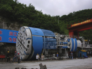
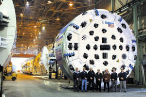
The Robbins TBM excavated the Westbound running tunnels, consisting of four short headings that required a design allowing for swift retraction and re-launching. A second Double Shield TBM, operated by SELI, was used to excavate the Eastbound running tunnels. The Robbins High Performance (HP) Main Beam machine was designed using a segmented, bolt-only cutterhead for easier disassembly. During retraction, the outer components of the cutterhead were removed first. The shielded front section of the TBM, designed as an “umbrella”, was then retracted using hydraulic extensions. The extensions allowed the bottom, side, and roof supports to move radially inwards, reducing the machine diameter from 6.7 m (22.0 ft) when fully extended to just 6.1 m (20.0 ft) with removal of the shield assemblies.
To remove muck, Robbins designed an extensive conveyor system utilizing every commonly recognized type of belt conveyor to transport muck more than 370 m (1,200 ft) away from the jobsite. The system design involved nine separate conveyors handling muck simultaneously from the two tunnels. Two extensible fabric belt conveyors (914 mm/ 36 inches in width) traveled behind the Eastbound and Westbound TBMs, and dumped via a crown-mounted cross conveyor onto a single 1,863 m (6,100 ft) fixed-length conveyor mounted inside the submersed tube.
From the tunnel, muck was transported up the 23 m (75 ft) deep Queens shaft using a fixed-length, steel cable vertical conveyor. Once the muck reached the top of the shaft, it was transferred to the Rail Yard using three overland conveyors and a radial stacker. The second overland conveyor, 37 m (120 ft) in length, crossed Northern Boulevard, a major thoroughfare in Manhattan. This conveyor was designed as a completely enclosed box truss to eliminate debris from reaching the roadway, and sat approximately 6 m (20 ft) above Northern Boulevard and under pre-existing rail lines. Muck was then transferred from the overland conveyors to a radial stacker in the Sunnyside Rail Yard. The radial stacker rotated through 60 degrees to deposit muck in kidney-shaped piles with a capacity of 8,400 cubic meters (11,000 cubic yards).
Tunnel Excavation
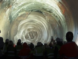
 The Robbins machine made four drives, totaling 5.2 km (3.3 mi) beneath Manhattan. The machine first bored 2.3 km (1.5 mi) towards Grand Central Station, and was then retracted 2.0 km (1.2 mi) through the newly bored tunnel, leaving all tracks and tunnel support structures in place. The machine was re-launched at a “Y” shaped intersection to bore three more tunnels at varying elevations.
Boring on the first tunnel commenced on September 30, 2008 with a total of 907 boring hours, and the second, 540 m (1,770 ft) tunnel was finished on February 20, 2009 after 267 boring hours. A third 1.7 km (1.1 mi) long tunnel was completed in February 2010. By June 2010, the machine had completed its fourth and last 630 m (2,060 ft) long drive after 281 boring hours. The conveyor system operated at over 90% availability during the course of the four headings.
At the time of completion for the Robbins Main Beam machine, the SELI TBM was being readied to bore the third of its four Eastbound running tunnels.
New Delhi Metro Extension Project
Project Overview
 Phase II of the New Delhi Metro Extension Project is an ambitious plan to add 53 km (33 mi) of new rail lines to cut transportation times, in particular for when the city hosted the Commonwealth Games in 2010. Owners Delhi Metro Rail Corporation (DMRC) completed Phase I of the project in November 2006, adding 65 km (40 mi) of track and 59 stations. Phase II, at a cost of USD $1.8 billion, involved multiple soft ground tunnels to be bored by Earth Pressure Balance Machines (EPBMs) between underground stations excavated by cut and cover.
On February 1, 2007, Robbins and Mitsubishi Heavy Industries (MHI) signed a contract with the CEC/Soma JV for two 6.5 m (21.4 ft) diameter EPBMs, back-up systems, and cutting tools. The machines were manufactured by Robbins using components from the U.S., India, and China.
On May 15 2008, the first of the two TBMs was launched from an 18 m (60 ft) deep shaft at the Jor Bagh station site. The machines bored parallel 2.0 km (1.2 mi) tunnels connecting the Udyog Bhawan and Green Park areas in New Delhi, as part of the BC-16 contract. The second machine was launched from the same site during the last week of June 2008.
Geology
The tunnels ranged from 8.6 – 14.0 m (28 – 46 ft) below the water table in sandy silt, silty sand and gravels.
Machine Design
Both EPB cutterheads featured a 55% opening ratio to allow a smooth flow of muck and to avoid clogging the cutterhead. The machines used several types of tungsten carbide bits for boring in soft but abrasive ground and shaft-type screw conveyors to remove water-bearing muck. Continuously erected lining along the length of the tunnel consisted of reinforced concrete segments 275 mm (11 in) thick.
Tunnel Excavation
 On September 29, 2008 the first of the two Robbins EPBMs completed its initial bore of 1.0 km (0.6 mi), holing through into the cut and cover Race Course station site. High advance rates of 19 rings installed per day, together with over 90% average availability, contributed to the fast completion. The machine was then dismantled in a reception pit and transported by road to the other end of the 318 m (1,000 ft) long Race Course site, where it began the second half of its bore to the contract boundary at Udyog Bhawan station. During excavation, the machine achieved a project record of 168 rings, or 202 m (663 ft) in one week—faster than any of the 14 other TBMs working on the project.
By April 2009, all four drives initially planned using Robbins machines were complete. Due to scheduling constraints, Continental Engineering Corporation (CEC) opted to use one of the Robbins machines for a fifth, approximately 567 m (1,860 ft) long drive from AIIMS to Green Park station sites. The fifth and last drive broke through on July 14, 2009.
The Abdalajis tunnels
Project Overview
 Spain’s high-speed rail network, known as AVE, involves links between the major cities Cordoba, Madrid, Seville, and Malaga. The twin 7.1 km (4.4 mile) long Abdalajis tunnels are part of this rail network and they will contribute to Spain’s overall goal to keep all major cities within four hours travel time from Madrid.
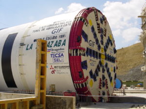
In 2001, the project owner Gestor de Infraestructuras Ferroviarias (GIF) awarded construction contracts separately for each tunnel. The east tunnel was awarded to a Dragados-led consortium called UTE Abdalajis, comprising Dragados, TECSA, SELI, and Jaeger. The west tunnel was awarded to a consortium called UTE Abdalajis Oueste (SACYR S.A., Somague-Engenharia). The two groups shared the main portal site and used nearly identical tunnel boring machines.
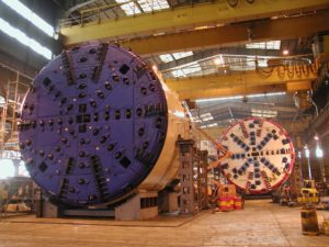
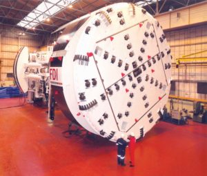
Both consortiums chose Double Shield TBMs designed by Robbins for Mitsubishi Heavy Industries. The machines were initially built in Spain by Duro Felguera. They were then assembled onsite with both Robbins and Mitsubishi technicians supervising the assembly.
Geology
The Abdalajis tunnels pass through a variety of rock types, including dolomitic limestone, quartzite, conglomerates, and sandstone. In the deepest part of the tunnels the strata is heavily fractured and karstic conditions in the limestone may harbor considerable amounts of water. The entire span of each tunnel contains more than twenty fractured and faulted areas.
TBMs
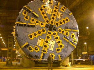
The TBMs featured sixty-four 17 inch (432mm) back-loading cutters and could generate a cutterhead thrust of 82,500 kN ( 18,546,734 lb). The Robbins Double Shield design generated a maximum cutterhead torque of 18,700,000 N-m (13,792 lb-ft). Both machines came with probe drills and foam application systems for face conditioning.
Tunnel Excavation
Excavation of the eastern tunnel began in November 2003. The custom design of the TBM allowed it to bore through brittle and heavily fractured rock efficiently. The TBM’s production rates along the first 1,590 m (5,217 ft) were very good with advance rates as high as 34 m (112 ft) per day.
In the middle of the tunnel bore, methane intrusions began to increase. Roughly 800 m (2,625 ft) of fractured clay with methane leaks forced stoppages to ventilate the tunnel. Despite these conditions the TBM kept a constant advance rate and encountered more stable limestone at the end of the tunnel before holing through in January 2006.
The west tunnel machine also began boring in November with similar broken ground and methane gas problems. Similar to the east tunnel TBM, the machine kept constant advance rates despite the unfavorable conditions. The TBM also encountered more stable limestone in the final meters of the tunnel. The west tunnel TBM finished roughly 2.5 months after the hole through in the east tunnel.
The Pajares Lot 4 tunnel
Project Overview
 The Pajares Lot 4 tunnel is part of Spain’s AVE high-speed rail link. The entire 49.5 km (30.8 mi) long tunnel connects Asturias to the Madrid-Valladolid high-speed link. The route was divided into four lots, with two tunnels for traveling both east and west.
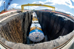
Project owner, Administrador de Infraestructuras Ferroviarias (ADIF), awarded the construction contract for Lot 4, a 10.5 km long section of tunnel, to a joint venture of Constructora Hispanica, Azvi, Brues y Fernandez and Copcisa. The joint venture chose a 10 m (32.8 ft) diameter Single Shield TBM to bore the tunnel. The TBM was designed by Robbins and built by Mitsubishi Heavy Industries. The machine was pre-assembled at a shop in Spain and final assembly was completed onsite.
Geology
The machine began boring in August 2006 through sandstone, shale, limestone, molasse, and volcanic rocks with Unconfined Compressive Strengths (UCS) of 40 to 90 Mpa (6-13 ksi). Robbins’ Single Shield design allowed the machine to cope with this fractured and varied rock. The machine could also erect 500 mm (19.7 in) thick pre-cast concrete segments to support the tunnel walls in troublesome geology.
TBM and Tunnel Excavation
 The TBM featured 17 inch (432 mm) cutters and was powered by 5,180 kW (6,946 hp) to generate a maximum cutterhead thrust of 16,814 kN (3,780,000 lb). The back-up system for the machine consisted of open gantries. Tunnel excavation was completed in July 2009.
The Niagara Tunnel Project
Project Overview
 The Niagara Tunnel Project is an ambitious project to tunnel 10.4 km (6.5 mi) from the Sir Adam Beck Generating Complex to above Niagara Falls. The new tunnel will increase the power supply for owner Ontario Power Generation (OPG) by 150 MW and will help to bolster the current power system, which is close to exceeding its capacity during peak months.
OPG awarded the construction contract to Austria-based Strabag AG, who chose a 14.4 m (47.5 ft) diameter Robbins Main Beam TBM to bore the tunnel. The setup included a 105 m (345 ft) long back-up system, which transported 1.7 million m3 (2.2 million cubic yards) of muck over three years via conveyor belt.
Geology
The tunnel is located predominantly in Queenston shale with some limestone, dolostone, sandstone and mudstone up to 200 MPa (29 ksi) UCS. The rock along the tunnel bore path is known to have high in-situ stress and there is potential for squeezing ground. An initial rock support lining of wire mesh, steel ribs, rock bolts, and shotcrete was installed as the TBM advanced. Behind the excavation, an in-situ placed concrete lining is being installed. The final lining will include a waterproofing membrane system to ensure that water does not seep from the tunnel into the rock and cause swelling.
TBM
The Main Beam TBM, the largest hard rock TBM in the world, was assembled at the jobsite using Onsite First Time Assembly (OFTA) in less than 12 months — ahead of a tight delivery schedule. The onsite assembly is considered unprecedented for such a large TBM. The TBM began boring in September 2006.
The Main Beam TBM was also the first ever to utilize back-loading 20-inch cutters, which increase cutter life and reduce cutter changes in hard rock. Both 19-inch and 20-inch cutters could be installed in the cutterhead. The machine had a cutterhead thrust of 18,462 kN (4,150,422 lb) and a maximum torque of 18,670,000 N-m (13,770,285 lb-ft).
Tunnel Excavation and World Records
After about 793 m (2,600 ft) of excavation the TBM entered the Queenston shale formation, where large rock blocks started to fall from the crown before rock support could be placed. In some cases, significant over-break up to 3 m (10 ft) above the cutterhead support was reported.
Strabag ultimately designed a unique ground support system to cope with the geology, which consisted of 9 m (30 ft) long pipe spiles in an umbrella pattern at the crown of the tunnel. Using the new spiling method, over-break was limited to about 0.9 m (3 ft) above the normal tunnel diameter. Nearly 500 m (1,640 ft) of very difficult ground was excavated using this method, at average rates of about 3 m (10 ft) per day.
The new ground support program, done for all excavated ground, consisted of 3 to 4 m (10 to 13 ft) long rock bolts, self-drilling (IBO) anchor bolts, steel straps, wire mesh and wire-reinforced shotcrete. Crews typically bored half a stroke, then began scaling down loose rock and installing rock bolts. After the full 6 ft stroke, the rest of the loose rock was scaled down before installing more rock bolts, wire mesh, steel straps and a layer of shotcrete.
OPG and the contractor also opted to alter the vertical alignment of the tunnel, raising it 46 m (150 ft) to move the tunnel out of the Queenston shale. After 1,981 m (6,500 ft), rock conditions were competent enough that spiling was no longer required.
After surpassing these challenging rock conditions, the machine achieved a world record-breaking month for any TBM 11 m (36 ft) in diameter or larger. During July 2009, the TBM excavated 468 m (1,500 ft) in one month and advanced 153 m (503 ft) in one week overcoming significant geological challenges.
Breakthrough
 May 13, 2011 marked the completion of the TBM’s drive. A well-attended ceremony celebrated the final breakthrough of the 14.4 m (47.2 ft) diameter Robbins Main Beam, following advance into a 300 m (1,000ft) long grout tunnel on March 1, 2011.
While the tunneling portion of the project has reached completion, two years of work still remain. Approximately 30% of the continuous concrete lining was completed during tunneling, with about two thirds of the work still to be done. The finished 12.8 m (42 ft) diameter tunnel will be fully lined with both 600 mm (24 in) thick cast in place concrete and a polyolefin waterproof membrane to prevent leakage. Other construction remaining includes the outlet structure, gates, and removal of the cofferdam in the Niagara River, as well as removal of the rock plug at the outlet end.
Mexico City Metro Line 12
Project Overview
 The Mexico City Metro is one of the world’s largest, with over 200 km (125 mi) of rail and nearly 4 million daily passengers. The 25.4 km (15.8 mi) long route passes through 22 new stations between Tlahuac and Mixcoac neighborhoods. The 7.7 km (4.8 mi) long tunnel represents the capital’s first new route in ten years, and will service thousands of passengers daily.
In 2007, the Mexican Federal District announced plans to build Line 12 of the Mexico City Metro. The ICA consortium signed a contract for a 10.2 m (33.5 ft) diameter Robbins EPBM, its back up system, and cutting tools. The TBM was the largest to ever bore in Mexico and was the first EPB TBM to be assembled at the jobsite using Onsite First Time Assembly (OFTA).
Geology
Geology on the metro line consisted of layers of clay, sand, and boulders up to 800 mm (30 in) in diameter, as the area is part of a drained lake bed. Ground conditions in Mexico City are very unique and thus required extensive vibration monitoring throughout the bore.
TBM
The giant machine utilized a specially designed two-stage, 1,200 mm (4 ft) diameter ribbon type screw conveyor followed by a shaft-type screw conveyor in order to handle the large boulders. For parts of the tunnel where the ground consisted of very soft clays with high water content, muck was removed using a sludge pump rather than conveyors or muck cars. The machine also featured active articulation, used to prevent segment ring deformation on curves as small as 250 m (820 ft). The spoke-type cutterhead used tungsten carbide knife-edge bits to excavate the soft ground. Additives, as well as two-liquid back-filling, helped control ground subsidence. The two-liquid back-filling system consisted of cement and accelerant, which hardens rapidly and eliminates the need for high-pressure concrete pumps that can disturb the ground. As the machine advanced, it lined the tunnel with 40 cm thick universal concrete segments in a 7+1 arrangement.
The Robbins EPB was launched on February 15, 2010, after just eight weeks of assembly. The launch shaft, approximately 34 m long by 14 m wide by 17 m deep (112 x 46 x 56 ft), was located in one of the most densely urban areas of the city. Due to the small launch pit, the machine bored the first 70 m (230 ft) of tunnel using umbilical cables connected to back-up gantries on the surface. Gantries were then lowered into the shaft successively as the machine bored forward.
Tunnel Excavation
Much of the tunnel was under very low  cover of 7.5 m (25 ft), which required careful monitoring of surface subsidence. The project’s location at the city center was in close proximity to a number of structures. The tunnel route took the machine within 1.5 m (4.9 ft) of a 4 m (13 ft) diameter collector sewer, within 2.0 m (6.6 ft) of building foundations, and just 3.5 m (11.5 ft) below the metro’s active Lines 2 and 3.
Breakthrough
The machine reached the its first station during the last week of April 2010 after boring a total of 495 m (1,624 ft). There were several difficulties with the sludge line, but after engineers redesigned the system it worked exceptionally well. From there, the EPB continued on to six more stations, undergoing routine maintenance at each one. On March 1, 2012, the machine completed its successful tunneling run.
Line 12 of the Mexico City Metro is the longest in the system. The new line carries an average of 367,000 passengers each day, making it the fourth busiest commuter rail route in the capital.
Locust Street Sanitary Improvements Project No. 6335
Project Overview
 In Tigard, Oregon, upwards of 1.8 km (1.1 mi) of gravity sewer were installed by general contractor Northwest Earthmovers Inc. for project owner Clean Water Services. Gonzales Boring & Tunneling was subcontracted to complete three crossings, which formed part of the Locust Street Sanitary Improvements Project No. 6335. The three crossings measured 70 m (230 ft), 183 m (600 ft), and 98 m (320 ft) in length. The 450 mm (18 in) diameter PVC carrier pipe was laid to increase wastewater capacity in the area and stop overflows currently plaguing the system.
Gonzales Boring & Tunneling purchased a Robbins 1.0 m (42 in) SBU-A to complete the three crossings located below houses, neighborhood streets, a small creek, and a service facility.
Geology
Rock conditions on the first crossing consisted of clay and basalt, while the second crossing was composed of basalt at various rock strengths ranging from 48 to 82 MPa (7,000 to 12,000 psi). Sections of the crossings were also interspersed with dirt containing small boulders.
SBU-A Features
Robbins SBU cutterheads can be equipped with a variety of tungsten carbide bits and single or multi-row disc cutters depending on the ground conditions. The SBU cutterhead for the Gonzales Boring crossings was fitted with 165 mm (6.5 in) single disc cutters and larger muck bucket openings to handle the mixed ground conditions.
During the launch of the machine, the SBU-A was welded to the lead steel casing. The cutterhead was propelled forward via torque and thrust from the Auger Boring Machine (ABM). Spoil was removed through openings in the cutterhead called muck buckets and discharged using a full-face auger.
Tunnel Excavation
 Workers monitored line and grade, and were able to maintain advance rates of 12 m (40 ft) per 10-hour shift. Using a contractor-designed steering system, the SBU-A holed through within one hundredth of an inch design grade after 183 m (600 ft) of excavation. In addition to having the record for the longest single crossing length, 183 m (600 ft), the machine required no cutter changes after 250 m (830 ft) of boring. A third crossing of 98 m (320 ft) was also excavated in early 2010.
Dahuofang Water Tunnel
Project Overview
 The Dahuofang Water Tunnel is a large reservoir diversion project that will transport water from high rainfall areas to the dry, heavily industrialized Shenyang region of China. The total length of the tunnel is 85.3 km (53 mi) with over 60 km (37 mi) being driven by tunnel boring machines (TBM) — one of the world’s longest TBM-driven tunnels.
Geology
The project owners awarded construction contracts in three lots, each about 20 km (12 mi) long. Lot 1, awarded to Beijing Vibroflotation Engineering Co Ltd, chose an 8.03 m (26.3 ft) diameter Robbins Main Beam TBM for the project. The machine is responsible for a 20 km (12 mi) bore in migmatite and orthopyre geology.
The Lot 3 contract was awarded to The Bureau of Water Conservancy and Hydroelectric Power Construction, who chose a nearly identical 8.03 m (26.3 ft) diameter Robbins Main Beam TBM for a 16 km (10 mi) long bore. This section of tunnel also passes through migmatite geology, but about two-thirds of the tunnel contains a complex mixture of heavily weathered and fractured rock.
TBMs
Both Robbins Machines include forty-three 19 in (483 mm) cutters and eight 17 in (432 mm) center cutters. The cutters are backloading with frontloading optional. Both machines use variable frequency drive systems and can generate a maximum thrust of 22,934 kN (5,155,767 lb) and the cutterheads of both machines have a torque of up to 6,275,000 N-m (4,628,202 lb-ft).
Robbins also provided the back-up systems for both machines. Each back-up includes a bridge conveyor, transfer conveyor, track-laying area, and rolling gantries among its units. The TBMs use slightly different conveyor systems — the conveyor for TBM 3 is a shorter length with a consequently reduced power-drive system.
The TBM accessory equipment mounts included probe drills and rock bolting systems, which are compact for working in limited space.
Tunnel Excavation
The Robbins TBMs began boring in June and July of 2005. In March of 2006, after only 8 months of boring, TBMs 1 and 3 had advanced 3.8 and 4.0 km (2.4 and 2.5 mi), respectively. The TBMs completed tunneling in 2007.
The Manapouri Hydroelectric Project
Project Overview
 The Manapouri Hydropower Station is the largest hydropower station in the country and supplies 5100 GWh of electricity annually. In 1997, the project owners, Electricity Corporation of New Zealand (ECNZ), proposed an expansion of the hydropower station from its then output of 585 MW. The plan included a second 9.6 km (6.0 mi) long tailrace tunnel connecting the underground power station at Lake Manapouri to its discharge point in Doubtful Sound.
In 1997 ECNZ awarded the construction contract, worth US $85 million, to a Joint Venture of Fletcher Construction (New Zealand), Dillingham Construction (U.S.), and Ilbau (Austria). The joint venture awarded the contract to Robbins for one 10.05 m (33.0 ft) diameter Main Beam TBM to excavate the tunnel.
Geology
The tunnel passed through Paleozoic metamorphic and igneous rocks. The metamorphic rocks included gneiss, calcsilicate, quartzite, and intrusions of gabbro and diorite. The tunnel geology also included five sub-vertical fault zones with high potential for water inflows.
TBM
Robbins designed the 10.05 m (33.0 ft) diameter TBM for the mixed face hard rock conditions in the tunnel. The Robbins design was then built by Kvaerner-Markham (U.K.) and shipped to the job site. The cutterhead featured sixty-eight 17 inch (432 mm) cutters with loading from either the front or back. Eleven two-speed electric motors powered the cutterhead with 3,463 kW (4,642 hp), generating a torque of 9,859,400 N-m (7,271,919 lb-ft). The 470 m (1,542 ft) long back-up system, built by Rowa Engineering, included a secondary rock-bolting station and a robotic shotcrete station.
Tunnel Excavation
 The Robbins TBM began boring in June 1998 and finished in 33 months. The tunnel progress was divided into four sections, or reaches. During Reach 1, about 1.8 km (1.1 mi) into the bore, the machine experienced few problems. During Reach 2 (spanning 2.4 km (1.5 mi)), the machine encountered heavy water inflows through the fault lines. These inflows reached proportions of 1,300 liters (343 gallons) per second and pressures up to 7.2 MPa (1.0 ksi). These high volumes of inflow necessarily slowed progress throughout Reach 2. Geological conditions improved in Reach 3 (spanning 2 km (1.2 mi)), and by Reach 4 (spanning the final 3.2 km (2.0 mi)) the machine was progressing at a substantial rate.
Despite setbacks due to water, the Robbins TBM suffered no major breakdowns and availability remained high throughout the dig. In addition, total TBM spare parts usage was far below the industry average for this type of job.
Kárahnjúkar Hydropower Project
Project Overview
 The Kárahnjúkar Hydropower Project created the Kárahnjúkar Power Plant to provide 4600 GWh of electricity annually to a nearby aluminum smelting plant. Three dams feed the main Hálslón reservoir and several other dams join the outflow in a combined headrace tunnel to an intake. The intake water travels to the powerhouse through two steel-line vertical shafts and exits from a tailrace tunnel that empties into the Jökulsá i Fljótsdal River.
Project owner Landsvirkjun awarded the construction contract for the hydroelectric project to the Iceland branch of Impregilo S.p.A. The contractor awarded the contract to Robbins for three Robbins Main Beam High Performance TBMs for three lengths of tunnel.
Geology
The machines began boring between April and September 2004 in basalt, moberg, and pillow lava geology up to 300 Mpa (44,000 psi) UCS. A number of fault lines and water inflows were encountered during boring, though the machines made good progress.
TBMs
All three TBMs were the first ever machines designed with back-loading cutterheadsfor 19” cutters. The successful design increased cutter life and reduced the time needed for cutter changes. All of the TBMs were equipped with probe and roof drilling capabilities and were specially designed for the ground conditions. The cutterhead designs featured rock deflectors to protect the cutterhead from fractured and blocky ground, as well as abrasion-resistant wear plates and carbide buttons to bore in abrasive rock.
Tunnel Excavation
Main Headrace Tunnel
By June 2006 the machines had made good progress despite difficult geologic conditions in the tunnels. TBM 1 finished its drive on September 9, 2006 after achieving impressive advance rates with a best month of 864.6 m (2,755 ft) in March 2006. On the same day, TBM 2 tied a world record in its size class after excavating 92 m (302 ft) in 24 hours. The TBM tied the record with another TBM that bored on the Epping to Chatswood Rail Link. TBM 2 finished its initial drive in Fall 2006 and was then disassembled and transported to bore an additional 8.7 km (5.4 mi) long section of the Jökulsá Diversion Tunnel in 2007. The third TBM finished its main tunnel drive on December 5, 2006. All of the TBMs achieved impressive monthly advance rates despite troublesome rock conditions.
Jökulsá Diversion Tunnel
 The Jökulsá Diversion Tunnel adds to the water supply capacity of the powerhouse by connecting the Ufsarlón Reservoir to the main headrace tunnel. Work began in April 2007 and finished in April 2008. During the 8.7 km (5.4 mi) drive, TBM 2 continuously turned in record-breaking performances, beating its own record in June 2007 by excavating 106.1 m (348.2 ft) in 24 hours.
In August 2007, the machine achieved the feat again by excavating 115.7 m (380 ft) in 24 hours and 428.8 m (1,400 ft) in one week. The machine excavated at consistently high rates and finished its bore on schedule.
Recent Posts
- Cooperative Innovation at the Manhattan Tunnel Project: Digger Shields with Expandable Segments to Excavate Complex Fill
- Robbins celebrates TBM acceptance for Ellicott City North Tunnel
- Huge Robbins Slurry TBM breaks through in Hiroshima
- Robbins TBMs break through at Delhi Metro DC-07 Project
- RETC 2025