 Close
Close  Menu
Menu 
Archives: Projects
Dulles Airport Train System
Swift Single Shields Excavate Dulles Airport
Project Overview
 With more than 27 million passengers a year, the Dulles International Airport is one of the busiest hubs in the country. The Metropolitan Washington Airports Authority, project owner, created a scheme to maximize transportation efficiency at the airport via an extensive subway system. The new rail line, called the Airport Train System (ATS), was designed to eliminate the previous system of rubber-tired surface vehicles, which added to airport congestion. The USD $1.2 billion project includes a fleet of 29 rail cars capable of traveling up to 68 km/hr (42 mph) between stations.
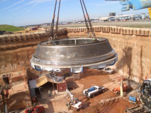
While excavated using a variety of methods, a 560 m section needed to be TBM-driven due to the location of an active concourse directly overhead. The Atkinson/Clark/Shea JV, contractor for the twin tunnels, awarded a complete contract to Robbins in 2004for two 6.4 m (21.1 ft) diameter TBMs, back-up systems, cutters, and spare parts.
Geology
The tunnel passed through mudstone, sandstone and siltstone geology from 32 to 48 MPa (4,700 to 7,000 psi) UCS. Conditions in the tunnel required immediate grouting at the tail shield to limit settlement.
TBMs
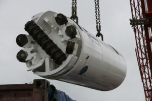
The owner specified Single Shield TBMs due to the short tunnel lengths, tunnel lining requirements, and immediate grouting requirements. Robbins refurbished the Single Shield TBMs, which were originally built in 1985 for the Taipei Metro Subway. Each machine received a new cutterhead, back-up system, thrust controls, and segment erector.
The machines were fitted with 15″ diameter disc cutters to bore in relatively soft rock. The back-up system was designed as an open gantry system for single-track muck cars.
Tunnel Excavation
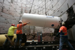
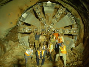 Each of the TBMs bored two tunnel drives, 460 m and 100 m (1,500 ft and 335 ft) in length. The TBMs bored the first 460 m (1,500 ft) section and were then walked through the 180 m (600 ft) long Concourse B station, excavated by cut and cover, to their second heading. While the TBMs bored, precast concrete segments were erected within the TBM tail shield to form the tunnel lining. Both TBMs had to maneuver through sharp turns with radii of 125 m (410 ft) as they approached the Main Terminal.
The machines broke through in September 2006. Many other methods including the New Austrian Tunneling (NATM) method and digger shields were used on the project as well. Phase 1 is slated for completion in 2009 and will provide rail service from both Concourse B and Concourse C to the main Terminal.
Milford Haven Gas Connection Project
Motorized SBUs Power through Rock on U.K. Pipeline
Project Overview
 In one of the U.K.’s most extensive infrastructure developments, the Milford Haven Gas Connection Project extends over 300 km (190 mi) across South Wales. The pipeline was created to deliver liquefied natural gas (LNG) from a port at Milford Haven, providing up to 20% of the U.K.’s natural gas for owner National Grid.
Constructed in two phases, work began on the pipeline in early 2006. Both phases were finished in November 2007. Phase I involved a 120 km (75 mi) long stretch from the towns of Milford Haven to Aberdulais. Phase II of the project extended the pipeline another 185 km (115 mi) from Felindre to Tirley in Gloucestershire.
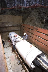
General Contractor NACAP/Land & Marine constructed many of the crossings for both Phases I and II, subcontracting some hard rock crossings to local contractor B&W Tunnelling Ltd. B&W utilized three 1.2 m (48 inch) Robbins SBU-As and two 1.2 m (48 inch) Robbins SBU-Ms to excavate 62 crossings ranging from 20 to 80 m (65 to 260 ft) in length.
Geology
The majority of crossings were located in siltstone and mudstone rock (70 to 200 MPa/ 10,000 to 29,000 psi UCS), with some interbedded clay and gravel.
Motorized SBU
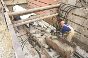
B&W Tunnelling opted for the Motorized SBU (SBU-M) due to the challenging contractual line and grade restrictions on their four longest bores. The 50 mm (2 in) tolerance meant they needed a machine with increased accuracy and continuous monitoring.
The Motorized SBU is a manned-entry, hard rock boring machine used for longer bores (over 150 m/ 500 ft in length) and for line- and grade-critical crossings. The machine is used in conjunction with a standard Auger Boring Machine (ABM) or pipe jacking unit and is welded to the lead casing in the same fashion as SBU-As. The machine is continuously steered from an operator’s console inside the rear shield, and uses a laser targeting system to monitor the machine’s heading.
B&W utilized two Motorized SBUs, one for hard rock and one for mixed ground. The mixed ground cutterhead featured 9.5″ diameter single disc cutters and larger muck openings to tackle the sections of rock interbedded with clay and gravels.
Tunnel Excavation
 All crossings were excavated successfully, typically averaging from 1.5 to 2.0 m (5.0 to 6.5 ft) per hour. Each of the SBU-A crossings utilized a 1.2 m (48 inch) ABM and required shallow launch pits measuring 24 m (80 ft) long x 3 m (10 ft) wide. Incredibly, the three SBU-A machines completed 53 crossings of 30 m (100 ft) in length (a total of approximately 1,600 m/ 5,300 ft bored) with only a single cutter change.
Each of the Motorized SBU crossings required the use of 10 to 30 m (33 to 100 ft) deep launch and recovery shafts. The 10.5 m (35 ft) diameter shafts were lined with concrete-bolted segmental rings and were used to install the pipeline after the crossing had been excavated. Sacrificial casing (steel, 1.2 m/ 48 in O.D.) was used to provide the necessary forward thrust to the cutting face from the ABM. The pipe was later removed and a semi-automatic welding bug was used to install the final pipeline.
Chester Boulevard Interceptor Sewer
Rockhead Makes Short Work of Indiana Crossings
Project Overview
 The city of Richmond, Indiana is a growing community of 50,000 people. To meet future projections, the city created a plan to double the current capacity of its sewer system via a 6.4 km (4 mi) long extension. The new gravity sewer would also eliminate the need for costly pump stations.
In December 2006, the Richmond Sanitary District awarded a USD $4.7 million contract to general contractor Brackney, Inc for construction of the Chester Boulevard Interceptor Sewer—a 3.2 km (2 mi) stretch of the new pipeline to provide service to a commercial district and nearby hospital. Subsequently, Midwest Mole, Inc. was subcontracted by Brackney to excavate four hard rock crossings underneath a river and historic walking trails. Midwest Mole opted to use a 1.2 m (48 inch) diameter SBU-A for the two shortest bores (55m / 180 ft in length), and a 1.4 m (54 inch) Single Shield Rockhead for the two longest bores of 120 m (400 ft) each.
Geology
The crossings were located in shale and limestone rock up to 70 MPa (10,200 psi) UCS. All of the crossings were in competent ground with little to no water inflows.
Rockhead
 Rockheads are the most efficient technology for hard rock or mixed ground conditions from 25 to over 175 MPa (4,000 to over 25,000 psi) UCS that are above the water table. Midwest Mole decided on a Robbins Rockhead for the longest bores due to the length of the crossings and the strict line and grade requirements. Both crossings required accurate excavation at a grade of 0.25%–an easy feat for the Rockhead, which is continuously steered via an operator’s console inside the machine’s rear shield.
The cutterhead on the 1.4 m (54 inch) machine was fitted with 6.5″ diameter patented Single Disc Cutters for optimal boring in solid rock. The machine is owned by Midwest Mole and had been used on six previous projects since 2005. After boring over 1,200 m (3,900 ft), the machine was sent in to the Robbins shop for its first refurbishment and change of cutters prior to the set of gravity sewer crossings.
Tunnel Excavation
Midwest Mole excavated the first 120 m (400 ft) long crossing in March 2007. The Rockhead was welded to the lead 1.4 m (54 in) diameter steel casing and launched from the bore pit using a pipe jacking system. The machine averaged 6 to 8 m (20 to 26 ft) per 10-hour shift, finishing both on time and within grade requirements.The second crossing excavation began in May 2007, with the machine accomplishing even better excavation rates of up to 9 m (30 ft) per shift.
Both SBU-A crossings were finished with similar results. Each of the 55 m (180 ft) crossings, on a 0.42% grade, required continuous monitoring of the machine’s heading. Stabilizer pads, located in each quadrant of the machine, were used to stabilize the machine and allow for steering during the first 6 to 8 m (20 to 26 ft) of the bore. Crews adjusted the machine’s heading by changing the height of the stabilizer pads using a hydraulic cylinder. After the first 6 to 8 m (20 to 26 ft), monitoring alignment required the use of a dutch level. If the alignment had drifted the auger was then pulled and reset on the correct heading. The machine averaged up to 6 m (20 ft) per 10-hour shift on both crossings.
Svartisen Hydroelectric Project
Project Overview
 Approximately 99 percent of the total electric power in Norway is derived through hydroelectric projects, making these large schemes a key part of the country’s infrastructure. Norway’s use of hydropower dates back to 1877, when its first hydro project reached completion. By 1990, Norway had more than 170 underground hydro facilities comprising approximately 3,500 km (2,175 mi) of tunnels throughout the country. Owner-contractor Statkraft plans, builds and operates all central government hydropower plants, which produce 28 percent of Norway’s total annual hydroelectric power output. The Svartisen project, located just north of the Arctic Circle, consists of 46 shafts connected to 40 km (25 mi) of 3.5 m (11.5 ft) to 5 m (16.4 ft) diameter tunnels. The tunnels are designed to collect and carry water from the glacier-covered Trollberget Mountains to Lake Storglomvatnet, the project’s reservoir. From there, the water is fed through a 7 km (4.4 mi) headrace tunnel to a sea-level power plant at Kilvik, Holandsfjorden. There are also two gutter tunnels to catch additional water from hillside inlets.
In 1988, Statkraft contracted Robbins to supply five machines to bore 57 km (35 mi) of tunnel for the new Svartisen Hydro Project, or 62 percent of the tunnels needed for the project. Two of the machines were veteran TBMs, 8.5 m (27.9 ft) and 3.5 m (11.5 ft) in diameter, and bored 7.3 km (4.4 mi) and 15.4 km (9.6 mi) of tunnel, respectively. Also employed on the project were three new Robbins High Performance (HP) TBMs capable of high thrust loads up to 312 kN per 19 in (483 mm) cutter. These first HP TBMs were revolutionary machines that paved the way for hard rock tunneling as we know it today.
Geology
The area’s geology consisted mainly of mica schist and mica gneiss (80 percent); metasandstone (pure quartzite), granite and granitic gneiss (13 percent); and limestone and marble (7 percent). The limestone beds varied in thickness from a few centimeters to more than 100 m (328 ft). Caves and underground drainage features were evident from the surface as well. The unconfined compressive strength of the Svartisen geologic formations varied from 100 MPa to more than 300 MPa (43,500 psi). Also, the steep, uneven topography caused irregular stress on rock masses which were subject to extreme tectonic and residual pressures. Because stable, hard rock conditions were present in more than 95 percent of the tunnel, no lining was required.
High Performance TBMs
All three HP machines were equipped with 19 in (483 mm) diameter disc cutters, which were developed by Robbins for the Svartisen Project. In addition to the larger cutters, the machines were built stronger than standard TBMs and had tri-axial main bearings to withstand higher loads. The two 4.3 m (14.1 ft) diameter HP machines weighed 262 metric tons (289 US tons) and supplied 2,345 kW (3,143 hp) of power to their cutterheads, allowing each machine to reach 9,048 kN (2,034,071 lb) of thrust at the face. A conversion kit was supplied for one of the machines that allowed it to bore at 5 m (16.4 ft) diameter instead of 4.3 m (14.1 ft) and also added six cutters, bringing the total weight of the machine to 290 metric tons (319 US tons). The third HP machine, weighing 180 metric tons (198 US tons), was 3.5 m (11.5 ft) in diameter and was supplied with 1,340 kW (1,796 hp) of power to the cutterhead giving it a total 7,800 kN (1,753,509 lb) of thrust. The cutterhead featured twenty-five 19 in (483 mm) diameter disc cutters.
In addition to higher penetration rates and advance rates, the new generation of TBMs enabled efficient use of the crew. Each machine was teamed with a back-up system equipped with remote controls and television cameras, and only required a four-person crew per shift – one to operate the machine and load the rail cars, a locomotive operator, an electrician and a mechanic to handle the extension of rail, cables, ventilation and hoses.
Tunnel Excavation
 All three HP machines achieved very impressive results throughout the project. The first of two 4.3 m (14.1 ft) diameter machines excavated 6,021 m (19,754 ft) of tunnel between September 1989 and October 1990, averaging 3.8 m (12.5 ft) per hour on its first drive. In its 5 m (16.4 ft) mode, it averaged 2.74 m (9 ft) per hour. The machine had a best day advance of 75.8 m (248.7 ft), best weekly advance of 312 m (1,024 ft) and best month of 1,068 m (3,504 ft) which were all Norwegian records.
The second 4.3 m machine bored 11,861 m (38,914 ft) of tunnel between September 1989 and April 1991, averaging 3.5 m (11.5 ft) per hour. In the process, the TBM set world performance records for machines in its 4 to 5 m ( 13 to 16 ft) diameter size class: best shift of 61.2 m (200.8 ft), best day of 90.2 m (296 ft), best week of 360.5 m (1,182.7 ft) and most material excavated in 24 hours: 1,309 m3(1,700 cubic yards).
The third machine began boring in July 1990 from a junction about 4 km (2.5 mi) from the crosscut area. In May 1991, about 4,700 m (15,420 ft) into the drive, the machine experienced poor ground and water inflows which slowed excavation for about 4 months. However, despite the poor conditions, the machine still averaged an overall advance rate of 3.7 m (12.1 ft) per hour while capturing a single shift record of 55.5 m (182.1 ft).
Ceneri Base Tunnel
Project Overview
 The AlpTransit Project is a massive rail project designed to provide more efficient rail freight routes via base tunnels through the Gotthard and Ceneri mountain ranges. Currently, freight trains traveling up the mountain ranges require pushing locomotives due to steep gradients. The base tunnels will provide a route for freight trains with minimum elevation gain and will shorten passenger train times between Zurich and Milan. Some route times, such as the trip between Lugano and Bellinzona, will be cut in half with the completion of the Ceneri tunnel. The Ceneri Base tunnels and the Gotthard Base tunnels will combine to create a new rail system that will span over 70 km (43 mi) of TBM-driven tunnels and 16 years of construction. The completed rail line is expected to open to traffic in 2019.
In April 2007, Contractor Consorzio Monte Ceneri (CMC) JV – a consortium of CSC, Lugano, Frutiger SA, Thun, Rothpletz, Lienhard + Cie, and Aarau, signed a contract for a 9.7 m (31.8 ft) Robbins machine to bore a 2.4 km (1.5 mi) adit on the Ceneri Base Tunnel Project. The completed adit tunnel joins up at approximately the halfway point of the main rail tunnels. The Main Beam TBM was completely refurbished near Milan, Italy where the cutterhead diameter was changed from 7.6 m (24.9 ft) to 9.7 m (31.8 ft). The TBM was the first machine on the AlpTransit project to utilize 483 mm (19 in) cutters, designed to offer a higher cutter load and longer cutter life resulting in fewer cutter changes. The refurbished machine previously bored successfully on the main headrace tunnel of the Kárahnjúkar Hydropower Project in Iceland.
Geology and Ground Support
Rock in the area consists of schist, Swiss molasse, and Ceneri orthogneiss with a UCS of 30 to 130 MPa (4,300 to 18,800 psi). Much of the tunnel was excavated under high cover of 600 m (2,000 ft). The geology of the tunnel alignment was good for TBM boring, with no squeezing ground or large water inflows encountered. New probe drills, designed in Robbins U.S. locations, were used to verify ground conditions ahead of the TBM. Temporary tunnel support including rock bolts, ring beams and shotcrete were also used depending on geology. Excavated material was temporarily stored at a lot onsite for later preparation as rock aggregate for concrete.
Tunnel Excavation
 On November 6, 2008 excavation of the adit tunnel was completed on schedule after only ten months of boring. Only 30 cutter rings were changed during the last kilometer of boring, with the cutters excavating a combined 160,000 cubic meters (5.9 million cubic feet) of hard rock. Daily advance rates averaged 18.5 m (60.7 ft) – about 61% higher than averages achieved by similar machines boring the Gotthard Base Tunnel using 432 mm (17 in) cutters.
Olmos Trans-Andean Tunnel
PROJECT OVERVIEW

The Olmos Trans-Andean tunnel has been more than 100 years in the making, with several attempts made in the 1950’s using drill and blast techniques. The tunnel, more than 20 km (12 mi) long in total, transfers water from the Huancabamba River on the Eastern side of the Andes to drought-ridden areas on the Pacific Ocean Watershed via a tunnel bored through the continental divide. The first phase also included a 43 m (140 ft) high dam diverting the Huancabamba River near the village of San Felipe through the mountains to the dry Olmos River on the Pacific side. Once the first phase of the tunnel project was operational, the scheme supplied more than 2 billion cubic meters (500 billion gallons) of water annually for irrigation of 560 km2 (130,000 acres) of farmland. Phases that followed included two more drill and blast tunnels, two hydroelectric stations generating 600 MW each, and a canal system to filter water throughout the coast.
GEOLOGY
The machine bored in complex geology consisting of quartz porphyry, andesite, and tuff from 60 to 225 MPa (8,700 to 32,600 psi) UCS. Over 400 fault lines were present along the entire tunnel, including two major fault lines approximately 50 m (160 ft) wide.
The overburden created another problem — high in-tunnel temperatures exceeded 54 degrees Celsius (130 degrees Fahrenheit). To cope with the high temperature Robbins designed the machine with a unique ventilation and air cooling system. Two interacting systems were used to cool the tunnel to 32 degrees Celsius (90 degrees Fahrenheit) or below. The high jobsite elevation (1,080 m / 3,500 ft) resulted in less dense air and less heat transfer capacity per cubic meter of air, so the two systems made it possible to blow more air into the tunnel for a maximum cooling effect.
TUNNEL EXCAVATION

Starting in late 2008, the TBM entered sections of high cover where crews experienced large overbreaks and cathedralling, along with rock bursting that could not be contained using wire mesh, rock bolts and ring beams. To better contain the fractured rock, Robbins and Odebrecht elected to make changes by installing a novel type of TBM ground support. The machine’s roof shield fingers were removed and replaced with the McNally Support System.
The McNally system works by replacing the curved finger shield plate for a curved assembly of pockets with rectangular cross-sections. The pockets extend axially from the rear side of the cutterhead to the cutterhead support, within the area where roof drills can work. Before a TBM stroke, crews slide slats of metal or wood into the pockets, such that the slats are two rows deep inside each pocket. The ends of the slats protrude from the pockets and are bolted to the roof of the tunnel using a steel strap. As the machine advances, the slats are extruded from the pockets and continuously bolted to the roof using subsequent straps. Slats are reloaded and used for the length of the tunnel to prevent deformation and rock falls.
Tunneling through the fractured and broken rock also created undue wear on the cutterhead. To cope with the problem, Robbins engineers added 19 mm (0.75 in) thick wear plates and 50 mm (2.0 in) thick square bars, known as ‘Boomerangs’, in front of each cutter. The boomerangs protect each cutter hub from blocky rock and bursting at the face.
Since modifications were done to the TBM, advance rates steadily improved, with the machine boring as much as 674 m (2,211 ft) per month. The improved rates were all the more remarkable considering two hazardous local floods in April 2008 and March 2009, which both inundated the site with more than a meter of mud and wiped out access roads.
After four years of extreme excavation through high cover and volcanic rock conditions, TBM tunneling at the Olmos Trans-Andean tunnel was completed on December 20, 2011 with an elaborate ceremony to celebrate the breakthrough.
Guangzhou Metro, GuangFo Line
Project Overview
 Since 2006, China has invested nearly USD $200 billion in rail infrastructure – a plan that promises to be one of the largest national railway expansions since that undertaken by the U.S. in the 19th century. Guangzhou’s metro expansion is part of the Pearl River Delta Inter-City Rapid Rail Project and China’s first ever inter-city rail link. The 32.2 km (20 mi) Guang-Fo line running between Guangzhou and Foshan was awarded in 12 separate lots. The owner, Guangzhou Metro Company, chose to utilize 16 different TBMs.
Lot 12, running between Jushu, Xilang, and Hedong stations, was awarded in 2007 to the China Communication Construction Corp., 2nd Navigation Engineering Bureau Ltd. (CCCC). The contractor, CCCC, selected two 6.3m (20.5 ft) diameter Robbins EPBMs for the parallel 2.6 km (1.6 mi) long rail tunnels. The two cutterheads began turning in January and February 2009, after being launched from the cut and cover site of Jushu station in southern Guangzhou.
Geology
The geology on the metro’s Lot 12 consisted of a complex layered profile, ranging from highly weathered to slightly weathered granite, coarse sand, and silt at pressures up to 4 bar. Around 70% of the tunneling was through a mixed face, with the alignment above the spring line in soft soils and the bottom half of the tunnel in rock of at least 50 MPa (7,250 psi) UCS. The remaining 30% consisted of flowing sand with high water content.
EPBM
Both Robbins EPBMs were designed with spoke-type cutterheads including large opening ratios of 37%, which allowed for smooth flow of muck into the mixing chamber. Both 432 mm (17 in) hard rock single disc cutters and carbide bits were used to combat the mixed ground conditions expected.
Four independent foam injection points on the cutterhead were used to further consolidate the muck flow. Foam was used on the Guangzhou tunnels because it was less costly and it also reduced the required cutterhead torque. Muck was removed using an 800 mm (31.5 inches) diameter shaft-type screw conveyor due to the fact that no large boulders were predicted. Active articulation was chosen for this project, mainly because much of the transit twists beneath the city, with curve radii as small as 200 m (656 ft).
Tunnel Excavation
 The two Robbins EPBs were launched in December 2008 and January 2009 respectively. After only seven months of boring, the two machines achieved more than 16 project records including a best month of 377 m (1,235 ft) – higher than any of the 16 TBMs that have worked on the Guang-Fo Metro Project.
Surface settlement was a major concern as the tunnels run beneath rivers, research sites, roadways, and vulnerable building foundations. Back-fill grout was used to fill the gap between the 300 mm (12 in) thick, pre-cast concrete segment rings and the surrounding soil. Some of the high-risk areas included the 80 m (262 ft) wide, 4 m (13 ft) deep Huadi River between Jushu and Xilang stations, and also the Pearl River Fisheries Research Institute, which has numerous sensitive ponds used for research into high-yield fish farming.
Both machines finished a month ahead of schedule, and operated around 95% availability. As of August 2009, only 66 disc cutters had been changed on the first machine and 46 on the second, while no carbide bits had been changed on either of the TBMs. The first machine completed its initial breakthrough into the Xilang station on August 15, 2009 and its final breakthrough in September. The second machine broke through into the Xilang station in September and made its final breakthrough in October 2009.
Glenwood Cable Tunnel
Project Overview
 EIC Associates were contracted in 2006 to construct over 13 km (8 mi) of a 115 kV power transmission line through Stamford, Darien, and Norwalk in Connecticut, USA. The final system includes three circuits consisting of 92 vaults and 62 handholds. EIC used a Robbins 1.5 m (60 in) Double Shield Rockhead (SBU-RHDS) to excavate two crossings under the Metro North Railroad in Darien, which turned out to be particularly difficult rock.
Due to the very poor ground conditions, G. Donaldson, a division of Hayward-Baker, Inc., was contracted to pre-grout utilizing two types of pre-grouting. The two types of grouting used were: horizontal grouting to stabilize the tunnel alignment, and vertical grouting around the road and rail structures to help reduce the risk of surface settlement.
Geology
Exploratory testing of the bore area found highly fractured meta-quartz monzonite ranging from 5,000 to 20,000 psi (35 to 140 MPa) UCS with Rock Quality Designations averaging 45%. Due to the unstable ground conditions, the location of the tunnel was lowered an additional 3 m (9 ft). However, further testing found extensive fractures here as well.
Rockhead
Rockheads are best suited for longer tunnels, where line-and-grade are critical such as in gravity sewers. EIC chose to use the best available option, the Robbins Double Shield Rockhead, due to the instability of the rock as well as the length of the bore.
The 1.5 m (60 in) diameter Double Shield machine, designed specifically for the highly fractured rock, featured a breasted plate cutterhead, which consisted of a steel plate in front of the standard cutterhead with slots for the single disc cutters. Grill bars were also added across the muck chutes to limit the size of rock allowed onto the conveyor.
Tunnel Excavation
 Excavation started in the spring of 2008, operating six days a week in two ten-hour shifts. The machine bored the two crossings averaging 254 to 635 mm (10 to 25 in) per hour, due to rock hardness. Using articulation cylinders and stabilizer pads, the machine was able to maintain line and grade throughout the bore. EIC elected to use reinforced concrete pipe for the lining, which was laid behind the machine using a pipe jacking system.
Throughout the bore, field service technicians adjusted the penetration rate of the machine, as pre-grouted sections made the rock face softer and easier to excavate. This adjustment required either a decrease in thrust cylinder pressure or cutterhead speed to avoid plugging the muck removal system with too much debris. The machine’s variable speed electric drive allowed for fine tuning throughout the drive.
Theun Hinboun Expansion Project
Project Overview

The Theun Hinboun Expansion Project is a hydroelectric project that requires a 5.5 km (3.4 mi) headrace tunnel bored by a Robbins Single Shield TBM – the first instance of TBM-driven tunneling in the country of Laos. Located on the banks of the Nam Theun River, the project consists of a new station, dam, and headrace tunnel which will add electricity supplies to Laos and neighboring Thailand by 2012. The USD $270 million project will address the power needs of the two countries by adding an additional 280 MW annual generating capacity. The original plant, built by Recchi-CMC JV between 1995 and 1998, already produces 220 MW annually. Power will be shared, with approximately 220 MW going to Thailand and 60 MW to the Laotian national power company, Electricite du Laos (EDL). The project also promises to improve the supply of electricity in Laos by extending the 115 kV transmission grid to the project area and increasing power supply to the existing grid.
Single Shield TBM Design
On December 22, 2008, CMC di Ravenna signed a contract with Robbins to provide a 7.6 m (15.1 ft) diameter Single Shield TBM. The TBM was assembled at Robbins’ Solon manufacturing facility in Ohio and shipped to the jobsite along the Nam Theun River. CMC di Ravenna chose the Robbins Single Shield for its short shield length, based on the geology and the need for continuous tunnel lining.
The Robbins TBM was designed to accommodate moderate squeezing ground conditions. Ground along the tunnel alignment consisted of alternating strata of sandstone, siltstone, and mudstone. An articulating cutterhead with overcutters allowed the machine to excavate 100 mm (4 in) beyond the nominal tunnel diameter. To support the ground and provide final lining, 280 mm (11 in) thick, pre-cast concrete segments were used in a 5+1 arrangement, making a finished tunnel diameter of 6.9 m (22.6 ft).
TBM Excavation
 During excavation, the Robbins Single Shield TBM averaged 19 m (62 ft) per day, with a peak advance rate of 37 m (121 ft) in one day. Ground conditions consisted of fair to good rock for 95% of the tunnel length, with some sections of poorer rock quality.
Challenging conditions included an anticipated 15 m (50 ft) wide fault zone at about the 4,700 m (2.9 mi) mark with flowing water. The crew was able to drill a borehole and use expanding foam to consolidate the ground, allowing boring to continue. The machine broke through on schedule, on November 21, 2010.
KOPS II Hydropower Project
Project Overview
 The KOPS II Hydropower project is located inside the Alps Mountains, drawing from the same reservoir as the KOPS I hydropower station, commissioned in 1969. The stations are supplied by the Rifa balancing reservoir, located between the tourist centers of Gaschurn and Partenen. The KOPS II pump station and headrace tunnel was built to supply power to the grid during peak demand and to ensure long-term network stability. Being that KOPS II uses the same reservoirs, no additional water was needed compared to KOPS I. Also, KOPS II uses an existing high-voltage line currently used by KOPS I.
Construction began at Kops II in 2004/2005, after Swietelsky Tunnelbau GmbH, Torno SA and Torno Int. S.p.A JV signed the contract for a 5.54 m (18.0 ft) Robbins Double Shield TBM. Construction of not only the tunnel, but the entire hydropower plant, was under strict watch as an Environmental Impact Assessment (EIA) was initiated. More than 500 regulations had to be followed assuring that construction would be done in an environmentally friendly way and in a tight time frame of 42 months.
The completed KOPS II plant provides an additional 450 MW in turbine mode and pump mode to the already existing 247 MW hydropower plant.
Geology
Geology on the tunnel alignment consisted of schist gneiss, migmatite gneiss, mica-schist, amphibolite gneiss, hornblende gneiss, granite-gneiss and aplite gneiss ranging from 30 to150 MPa (4,000 to 22,000 psi) UCS.
TBM Design and Tunnel Excavation
 The Robbins TBM used 483 mm (19 in) back-loading cutters to bore through the very challenging and mixed geology. The cutterhead was designed with 9,074 kN (2,040,000 lb) of thrust and 2,159,424 N-m (1,591,300 lb-ft) of torque. The TBM power was 1,575 kW (2,112 hp).
Boring commenced on the headrace tunnel on July 20, 2006. The TBM was one of the first machines to use a back-loading 19 inch cutterhead. The resulting cutter blockage percentage ratio was very low—only 2% over the duration of the project, compared to the more typical rate of 10-15%. The KOPS II pump storage plant went into operation in 2008.
Recent Posts
- Cooperative Innovation at the Manhattan Tunnel Project: Digger Shields with Expandable Segments to Excavate Complex Fill
- Robbins celebrates TBM acceptance for Ellicott City North Tunnel
- Huge Robbins Slurry TBM breaks through in Hiroshima
- Robbins TBMs break through at Delhi Metro DC-07 Project
- RETC 2025